
Installation Challenges for MCS: Infrastructure Requirements for High-Power Hubs
Quick Answer:
Installing a Megawatt Charging System (MCS) hub is fundamentally an electrical and civil-engineering project, not a hardware purchase. A single 1MW stall draws as much power as a small factory, and a four-stall hub can demand 4–6MW simultaneously — far beyond what most distribution feeders can supply without reinforcement. The core installation challenges are grid capacity and transformer sizing, high-current cabling and busbar design, liquid-cooling infrastructure, civil works and space, safety and code compliance, and multi-year utility interconnection lead times. The proven mitigation is to size the grid connection to average rather than peak load and buffer the difference with on-site battery storage, while specifying modular, liquid-cooled, 1,000V-ready power cabinets that can be staged incrementally as truck volume grows.
Key Takeaways:
- Grid capacity is the defining constraint. A typical MCS hub needs a dedicated medium-voltage service (1–6MW), often triggering transformer upgrades and utility studies lasting 12–24 months.
- Buffer with storage, not oversizing. A battery energy storage system lets a site connect on a smaller, cheaper feeder — the single largest CAPEX saving in MCS installation.
- Liquid cooling is a site utility, not a feature. Coolant distribution, heat rejection, and maintenance access must be designed into the layout from day one.
- Civil works are the least reversible cost. Trenching, foundations, and switchgear clearances should be provisioned for the site’s full megawatt build-out, even if phase one installs less.
- Modular, split-architecture cabinets de-risk installation. Separating power conversion from dispensers cuts cable runs, thermal load near the bays, and service downtime.
Why MCS Installation Is a Different Discipline
Most DC fast charging installations are site-works projects measured in weeks. MCS installation is closer to commissioning a small industrial facility. The reason is scale: a 1MW charger delivers roughly 2,900x the energy of a 350kW stall over the same session, and a busy truck hub may run four to eight such stalls. The electricity demand alone — 4–6MW at peak — equals that of a light manufacturing plant, and the associated infrastructure (transformers, switchgear, cabling, protection systems) must be engineered to industrial standards.
That means the project timeline for an MCS hub is dominated not by charger procurement but by grid interconnection, civil construction, and code approval. Operators who treat MCS as “a bigger charger to plug in” routinely discover that the electrical service, the concrete, and the permits take longer and cost more than the charging hardware itself. Understanding each challenge in advance is the difference between a 9-month build and a 30-month ordeal.
MIDA Power’s MCS-ready platforms are engineered with these site constraints in mind: modular liquid-cooled cabinets, split power/ dispensing architecture, and protocol-complete controls that simplify commissioning. But no hardware can eliminate the need for careful electrical and civil design — which is what the rest of this article covers.
Challenge 1: Grid Connection and Transformer Sizing
The first and largest obstacle is getting enough power to the site. MCS hubs are sized in megawatts, and most existing commercial or highway locations are served by feeders adequate for tens to hundreds of kilowatts, not thousands.
| Site Scenario | Peak Demand | Typical Existing Service | Required Action | Indicative Grid Lead Time |
|---|---|---|---|---|
| Single 1MW stall | ~1.0MW | 200–400kVA | New transformer + service upgrade | 12–18 months |
| Small hub (2–3 stalls, 1MW each) | 2–3MW | 400–630kVA | Dedicated MV service, new switchgear | 15–24 months |
| Full hub (4–6 stalls) | 4–6MW | <1,000kVA | Substation, possible feeder reinforcement | 18–30 months |
| BESS-buffered hub | 1.5–2MW grid draw | 250–630kVA | Transformer upgrade + storage | 9–15 months |
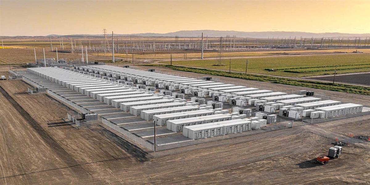
The table reveals the strategic lever: buffering with battery storage. By sizing the grid connection to the site’s average load rather than its peak, a hub that peaks at 4MW might draw only 1.5–2MW from the grid, served by the battery during charging surges and recharged during lulls. This can shrink the required service by 50–60% and pull the interconnection timeline forward by months — often the difference between a viable and a stranded project. MIDA positions integrated BESS + DC charging as the default architecture for exactly this reason, and pairs it with modular cabinets that draw power predictably across the site.
Challenge 2: High-Current Cabling and Busbar Design
Delivering 1,000A+ to a truck inlet is a cable-engineering problem. The conductors required are heavy, and their I²R losses generate significant heat that must be removed continuously. Two design approaches dominate:
- Liquid-cooled dispenser cables. Coolant circulates alongside the DC conductors inside the cable jacket, allowing a smaller copper cross-section and a lighter, more flexible cable. This is the same technology MIDA applies across its 40kW/60kW liquid-cooling power modules and high-power dispensers.
- Split power/ dispensing architecture. Centralizing power conversion in cabinets and running DC busbars to remote dispensers reduces the length of high-current cabling, cuts resistive losses, and keeps heat-generating electronics away from the charging bays. MIDA’s 480kW ultra-fast liquid-cooled station for motorways is a reference implementation of this split design, scaled into megawatt clusters.
Sites that ignore cabling design pay twice: once in higher material and installation cost, and again in efficiency losses and thermal derating that reduce delivered power.
Challenge 3: Liquid Cooling and Heat Rejection
Liquid cooling is what makes megawatt charging physically possible, but it introduces site-level infrastructure requirements that air-cooled chargers never impose:
- Coolant distribution. Cabinets and cables need a coolant loop with pumps, reservoirs, filters, and leak detection. For multi-stall hubs, a centralized coolant plant can serve several cabinets, simplifying maintenance.
- Heat rejection. The site must dissipate several kilowatts of heat per cabinet. Dry coolers or chillers must be placed with adequate airflow and acoustic clearance, which affects lot layout.
- Service access. Coolant top-up, filter changes, and pump service require maintenance access to cabinets — a layout consideration, not a field fix.
Designing for cooling from the start is far cheaper than retrofitting it. Because MIDA’s cooling architecture is modular and standardized across the 360kW liquid-cooled station with RFID, OCPP, and POS and larger platforms, service procedures and spare parts are consistent across a site’s entire cabinet fleet.
Challenge 4: Civil Works, Space, and Layout
MCS hubs are physically large. A truck-and-trailer combination occupies significant maneuvering space, and the layout must accommodate:
- Pull-through or nose-in bays sized for 16.5m trucks with turning radius clearance.
- Cabinet and transformer pads with protective bollards and code-mandated clearances.
- Coolant and cable routing trenches designed for the full build-out, even if phase one is smaller.
- Driver amenities — restrooms, lighting, food — which determine whether a 25-minute stop is pleasant or tolerated.
Because trenching, foundations, and switchgear concrete are the most expensive and least reversible elements, experienced developers provision them for the site’s eventual megawatt capacity. Adding a second or third cabinet later is cheap; re-excavating an operating truck yard is not.
Challenge 5: Safety, Codes, and Compliance
Megawatt-class DC systems fall under stringent electrical and fire-safety codes. Key requirements include:
| Requirement Area | Typical Standard / Provision | Installation Impact |
|---|---|---|
| Electrical safety | IEC 61851-23, UL 2202, local wiring codes | Arc-flash ratings, isolation, grounding |
| Connector & comms | CharIN MCS, ISO 15118-20, SAE J3271 | Certified connector, Plug & Charge support |
| Protection systems | Overcurrent, earth fault, insulation monitoring | Dedicated protection panel per cabinet |
| Fire & thermal | Battery/coolant fire strategy, thermal runaway mitigation | Detection, suppression, separation distances |
| Grid interconnection | Utility protection, anti-islanding, export rules | Relay coordination, utility witness testing |
Compliance is not a one-time gate — it shapes the layout, the protection scheme, and the commissioning sequence. Choosing hardware with pre-certified subassemblies shortens this phase because the highest-risk components already carry verified test data.
A Phased Installation Playbook
The most successful MCS deployments follow a staged sequence that matches capital outlay to truck volume:
- Phase 0 — Provision. Secure a site with room for the full build-out. Size grid studies and civil works for peak capacity. Establish a realistic interconnection timeline (assume 12–24 months).
- Phase 1 — Anchor. Install a limited number of liquid-cooled, 1,000V-capable stalls (e.g., 480–600kW) with the control plane and trenches ready for MCS. Serve early trucks on CCS2.
- Phase 2 — Buffer. Add battery storage to lift the effective peak without enlarging the grid contract, and to capture demand-charge savings.
- Phase 3 — Megawatt. Add cabinets and MCS connector heads as megawatt trucks arrive, reusing the same power modules, cooling, and controls.
This playbook converts the installation challenge — long grid lead times and heavy civil works — from a barrier into a phased, financeable program. Starting with modular MIDA hardware means each phase builds on the last rather than replacing it.
FAQ
1. How much grid power does an MCS charging hub need?
A single stall needs about 1MW; a four-stall hub can peak at 4–6MW. Most sites reduce the required grid connection by 50–60% using on-site battery storage to buffer peaks.
2. How long does MCS grid interconnection take?
Transformer and service upgrades typically take 12–18 months for a single stall and 18–30 months for a multi-megawatt hub, depending on the local utility and whether feeder reinforcement is needed.
3. Can I install MCS on an existing charging site?
Only if the site has adequate grid capacity, space, and modular liquid-cooled architecture. Many existing sites lack the service size or civil provisions and require significant upgrade or relocation.
4. Why is liquid cooling required for MCS installation?
At 1,000A+ continuous current, cables and connectors generate several kilowatts of heat that air cooling cannot remove at a practical form factor. Liquid cooling is a site-level utility that must be designed in.
5. What is the biggest cost in an MCS installation?
For most projects, grid interconnection and civil works — transformers, switchgear, trenching, and foundations — exceed the charging hardware cost. This is why provisioning for full build-out early is essential.
6. How can I reduce MCS installation cost?
Buffer the grid with battery storage, provision civil works for the full build-out, and stage power cabinets incrementally using modular hardware so first CAPEX is lower and expansion is non-destructive.
7. Do MCS hubs need dedicated on-site staff?
Not necessarily. Protocol-complete controls (OCPP 2.0.1, ISO 15118-20) and module-level telemetry enable remote monitoring and predictive maintenance, so a hub can be unattended while flagging service needs in advance.
Conclusion
MCS installation success is decided long before the first connector is energized — in grid studies, civil plans, and layout decisions. The operators who win are those who treat megawatt charging as an infrastructure program: secure the grid connection early, buffer it with storage, provision civil works for the full build-out, and deploy modular liquid-cooled cabinets that can be staged as demand grows. MIDA Power engineers its MCS-ready platforms for exactly this reality — split architecture, standardized liquid-cooled modules, and protocol-complete controls that turn a complex installation into a phased, financeable project. Explore MIDA’s high-power charging solutions to plan your hub.
Post time: Sep-10-2026


