
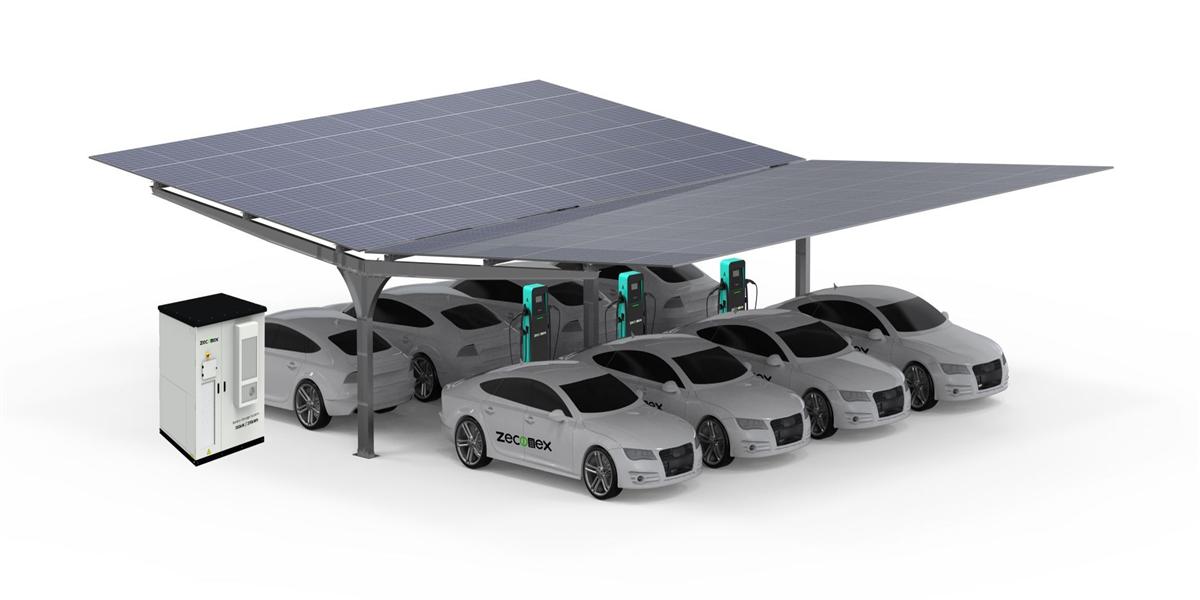
MIDA 240kW Solar-Integrated DCDC Fast Charging Station for Off-Grid EV Hubs
Quick Answer
A MIDA 240kW solar-integrated DCDC fast charging station puts the PV array, the battery energy storage system (BESS), and the DC charging outputs on one common DC bus, so solar and battery energy reach the vehicle without ever being converted to AC and back. That architecture cuts conversion losses to roughly 3–5% instead of the 8–14% typical of AC-coupled designs, and it is what makes a genuinely off-grid EV hub practical: an array of 250–400 kWp plus 200–600 kWh of LFP storage sustains 18–26 high-power charging sessions per day at a highway rest area, mine, depot, or island site with no utility feed. Diesel or a limited grid tie becomes backup only, and energy cost per kWh can fall 40–60% versus generator-only operation.
Key Takeaways
- DC coupling is the efficiency decision that matters most. A single DC bus for PV, battery, and charger output removes two conversion stages per kWh and lifts system round-trip efficiency to 92–96%.
- 240 kW of output is a site-level rating, not a single-cable rating. MIDA’s 240 kW platform distributes power across outputs via modular 20–40 kW wide-voltage charging modules, so a 60 kWh vehicle and a 300 kWh truck can share the same station intelligently.
- Sizing rule for off-grid hubs: 1.3–1.8 kWp of PV per kW of charger power, plus 1.5–2.5 kWh of storage per kW of charger power for overnight and low-irradiance continuity.
- Payback beats diesel fast. In remote and weak-grid locations, PV+BESS DCDC hubs typically reach simple payback in 4–6 years against diesel generation, and 2.5–4 years where a partial grid connection exists.
- Specify high-voltage DC (1,000–1,500 V) end to end — PV strings, battery rack, and charging modules — to reduce current, cabling copper, and resistive loss across the site.

Why Off-Grid EV Hubs Became a Real Market
For a decade, the answer to “can I build a fast-charging hub with no grid?” was always the same: yes, but you would pay diesel prices forever. That answer has changed. Three forces converged. First, PV module prices fell far enough that an off-grid array is now a capital cost measured in single-digit dollars per watt-peak installed, not the double digits of the 2010s. Second, LFP storage moved from a niche chemistry to the industrial default, with cycle life of 6,000–8,000 cycles at 80% depth of discharge and liquid-cooled racks that hold cell temperature variance within ±3°C. Third, DC-coupled power conversion matured: high-voltage MPPT charge controllers, bidirectional DC/DC converters, and wide-voltage charging modules now let solar, battery, and vehicle share a bus without a transformer stage in between.
The demand side is equally clear. Mining, agricultural, and construction fleets are being electrified by regulation and fuel-cost pressure. Highway rest areas with weak rural distribution need resilience, not just throughput. Island and coastal sites pay $0.35–0.70/kWh for diesel power, and logistics yards on a 400 kVA service cannot add 240 kW of charging without a six-figure transformer upgrade and a 12–18 month wait. In each case a solar-integrated DCDC station is the shortest path to a functioning site.
How a 240kW Solar-Integrated DCDC Station Actually Works
The architecture is best understood as one DC bus with three participants.
- The PV array feeds high-voltage strings into MPPT charge controllers (or, at larger scale, into a DC/DC PV converter stage). These track the maximum power point of the array and deliver voltage-regulated DC directly to the bus — no inverter, no AC coupling, no grid-frequency synchronisation.
- The battery energy storage system connects to the same bus through a bidirectional DC/DC converter. It absorbs surplus solar during high-irradiance hours, buffers the instantaneous load when a vehicle plugs in, and supplies energy after sunset or during cloud transients.
- The charging modules draw from the bus and regulate output to the vehicle’s battery through the connector. Because the bus is already DC, the module never rectifies AC; it performs DC/DC conversion with a wide output voltage window (typically 200–1,000 V, with 1,500 V-class modules available for heavy-duty vehicles).
The result is a fundamentally shorter conversion chain. In an AC-coupled site, energy travels PV → DC → AC (inverter) → AC bus → AC → DC (charger) → vehicle, plus the same double conversion on the storage side. Every arrow is a loss. In a DC-coupled 240 kW station, PV → DC bus → DC → vehicle, and storage → DC bus → DC → vehicle. Fewer stages, fewer losses, fewer failure points, and no need for the chargers to be synchronised to a grid frequency that may not exist.
Where the Charging Modules Fit
The charging module is the component that determines serviceability, scalability, and total cost of ownership. MIDA builds stations around modular wide-voltage units — the same charging modules for EV family used across its DC product range — so a 240 kW cabinet holds multiple independent modules feeding a shared output matrix. Three engineering consequences follow:
- Graceful degradation. If one module faults, the station continues delivering at reduced power instead of dropping offline entirely. For an off-grid site where the nearest service technician may be hours away, that is the difference between an inconvenience and a stranded hub.
- Right-sizing to demand. A depot that starts with a 120 kW requirement can scale to 240 kW by adding modules rather than replacing a cabinet, keeping the DC bus, PV array, and storage investment intact.
- Field-replaceable maintenance. Module swap is a service operation, not a factory return, which shortens mean time to repair and reduces spares inventory.
The EMS Layer
Above the power hardware sits the energy management system. At an off-grid hub the EMS has a harder job than at a grid-connected site, because it is the only authority on the bus. It forecasts solar yield from irradiance data and array geometry, learns the site’s vehicle arrival pattern, enforces battery state-of-charge limits (typically 10–90% for longevity), protects the battery from excessive C-rates during simultaneous sessions, and manages generator start/stop where a backup source exists. It also exposes the site to OCPP 2.0.1 backends for billing, roaming, and remote diagnostics. In a DC-coupled design, the EMS and the charger management system must be one coordinated controller; splitting them across two vendors is the most common cause of underperforming solar-charging sites.

What 240 kW of Output Really Delivers
Output rating and delivered energy are different numbers, and off-grid projects fail when the two are confused. The table below translates a 240 kW DC station with 350 kWp of PV and 400 kWh of storage into realistic daily throughput.
| Site type | Vehicles | Daily energy delivered | Sessions/day | Notes |
|---|---|---|---|---|
| Highway rest area (tropical, 5.0 kWh/m²/day) | LD passenger EVs | 1,200–1,800 kWh | 20–30 | 25–35 min sessions at 120–180 kW |
| Logistics depot (temperate, 3.5 kWh/m²/day) | Light commercial vans | 900–1,300 kWh | 12–20 | Two simultaneous 120 kW outputs |
| Mining / construction site | Off-highway trucks, 400–600 kWh packs | 1,400–2,000 kWh | 6–10 | Requires 1,500 V-class modules and liquid-cooled cables |
| Island / resort hub | Mixed LD and shuttle buses | 800–1,500 kWh | 10–22 | Diesel generator for multi-day cloud events only |
| Weak-grid depot (grid-assisted) | Mixed fleet | 2,000–3,000 kWh | 25–40 | Grid top-up at night, PV drives the day |
Two operational facts drive the design. First, a 240 kW station rarely runs all 240 kW for hours; the energy budget is driven by session volume multiplied by session energy, not by rated power. Second, storage exists to decouple the instantaneous load from solar availability — a 400 kWh pack at 80% usable depth provides roughly 320 kWh of buffer, which is 2–3 hours of continuous 120 kW output and enough to ride through a cloud front or a queue of two vehicles arriving at 21:00.
Sizing the Solar Array and the Battery
The two sizing equations below are the ones that determine whether the site works in February as well as June. Use worst-month irradiance, not annual average.
| Parameter | Practical formula | Example (240 kW station) |
|---|---|---|
| PV array size | 1.3–1.8 kWp per kW of charger power | 320–430 kWp |
| Storage capacity | 1.5–2.5 kWh per kW of charger power | 360–600 kWh |
| Storage power (PCS/DC-DC) | 0.8–1.2× charger rated power | 200–290 kW |
| Bus voltage | 1,000–1,500 V DC | 1,500 V preferred |
| Back-up generation | 15–25% of PV nameplate, if required | 60–100 kW diesel, duty-cycled |
| Ground area | 3.5–5.0 m² per kWp (fixed tilt) | 1,300–2,000 m² |
Three refinements matter in practice. Seasonal depth — a site in northern Europe may see 25–30% of June yield in December, so either the array grows or the storage grows to shift summer surplus forward. Arrival profile — a depot whose vehicles return at 17:00 needs storage power, not just storage energy, because it must both charge the fleet and absorb the last two hours of solar simultaneously. Redundancy — for a truly islanded site, split the array into two strings feeding separate MPPT channels and split storage into at least two racks, so a single fault never removes the whole energy source.
Efficiency, Loss Reduction, and the Numbers Behind the Claim
DC coupling is not a marketing slogan; it is a measurable loss reduction. A representative loss stack for a 100 kWh energy transfer looks like this.
| Conversion stage | AC-coupled system | DC-coupled DCDC system |
|---|---|---|
| PV DC/DC or inverter | 97.5% (PV inverter) | 98.5% (MPPT / DC-DC) |
| AC bus and transformer | 98.0% | Not present (DC bus: 99.5%) |
| Battery charge path | 96.0% (AC/DC bidirectional) | 98.0% (DC/DC bidirectional) |
| Battery discharge path | 96.0% | 98.0% |
| Charger AC/DC rectification | 95.5% | Not present |
| Charger DC/DC output stage | 97.5% | 97.5% |
| Effective PV-to-vehicle efficiency | ≈ 85–88% | ≈ 92–96% |
Over a site delivering 500,000 kWh per year, a 7-percentage-point efficiency advantage is 35,000 kWh of energy that no longer has to be generated, stored, and paid for — roughly the annual consumption of a small household per week, every week. Where energy is diesel-generated or grid-limited, that gap converts directly into capital avoided: a smaller array, a smaller battery, or one fewer module per cabinet.
Total Cost of Ownership: Off-Grid DCDC Hub vs Diesel and AC-Coupled Alternatives
| Cost element (10-year horizon) | Diesel generator + AC chargers | Grid + AC-coupled PV/BESS chargers | 240kW solar DCDC hub |
|---|---|---|---|
| Up-front equipment | $120k–$180k | $260k–$420k | $320k–$480k (with PV and storage) |
| Grid or generation connection | $0 (none) | $60k–$150k (often 12–18 months) | $0–$40k (weak-grid variant) |
| Fuel / energy cost | $0.45–$0.80/kWh generated | $0.10–$0.22/kWh blended | $0.06–$0.13/kWh blended |
| Maintenance (annual) | 6–9% of capex | 2–4% of capex | 1.5–3% of capex |
| Service availability | 85–92% (refuelling, breakdowns) | 97–99% (grid dependent) | 97–99% |
| Simple payback vs. baseline | baseline | 3–5 years | 4–6 years vs diesel; 2.5–4 years with weak grid |
The diesel comparison understates the case because it ignores emissions regulation, noise restrictions at residential or protected sites, fuel logistics in remote terrain, and the reputational cost of running a “zero-emission hub” on a generator. For logistics and municipal fleets reporting scope 1 and scope 2 emissions, a solar-integrated DCDC station is often the only configuration that satisfies both the energy requirement and the reporting requirement.
Deployment Scenarios and Design Notes
Highway rest areas with no viable feed. Combine a PV carport over the parking bays with a ground-mount array behind the site. Carports reduce land use, shade vehicles, and lower cable runs to the charging cabinets. Where a 200 kWh-class storage block is specified, the architecture mirrors MIDA’s 200kWh solar BESS EV charging station for zero-emission sites, scaled to the 240 kW output level.
Fleet depots with a weak grid. Keep a modest grid connection (100–250 kVA) for overnight replenishment and use the solar DCDC bus for daytime opportunity charging. This hybrid model delivers the highest equipment utilisation and the fastest payback of any configuration, because the storage cycle never runs empty for long.
Mining, quarry, and construction. Dust, vibration, and wide temperature swings dominate. Specify IP54-or-better enclosures, liquid-cooled cables and connectors, and connectors rated for the site’s fleet mix. Heavy-duty vehicles with 400–600 kWh packs require the full 240 kW and 1,500 V-class modules to charge within a shift break.
Islands and remote communities. Size storage for three consecutive low-irradiance days with no generator, two with a generator as the third layer, and specify remote diagnostics and OTA firmware updates — a technician visit here is measured in days, not hours.
Procurement Checklist for Off-Grid Solar DCDC Stations
- Confirm DC-coupled topology in writing. Ask the supplier to state PV-to-vehicle efficiency at the bus level, not the inverter datasheet number.
- Verify wide-voltage module range. Output must span the low-voltage (200–500 V) and high-voltage (up to 1,000 V, 1,500 V for HD) vehicle ranges without derating.
- Check connector portfolio. CCS1, CCS2, NACS, GB/T and CHAdeMO coverage determines which vehicle parc your site can serve.
- Require liquid cooling for anything above 120 kW continuous — modules, cables, and connectors — and confirm the ambient temperature rating at 45–50°C.
- Validate storage certifications. IEC 62619, UL 9540/9540A where applicable, plus fire suppression and thermal-runaway test evidence.
- Insist on OCPP 2.0.1 and ISO 15118 readiness for Plug & Charge, tariff handling, and future vehicle-to-site services.
- Ask for a twelve-month performance guarantee on solar yield and availability, with the simulation model handed over.
Why MIDA’s Solar DCDC Platform Fits Off-Grid Hubs
MIDA Power builds both halves of the equation — power conversion and energy storage integration — which removes the coordination risk that sinks most DC-coupled projects. The MIDA charging solutions portfolio spans portable chargers, AC wallboxes, DC cabinets and modules, and PV storage components, all engineered around the same wide-voltage, liquid-cooled design language. For sites that need to grow beyond 240 kW, the same engineering philosophy scales to the 600kW–720kW liquid-cooled DC charging station for EV truck and bus, where megawatt-class highway and depot hubs combine ultra-high-power outputs with the same DC bus architecture described here.
FAQ
1. Can a 240kW solar DCDC station truly run off-grid with no generator?
Yes, if the array and storage are sized for worst-month irradiance and the site’s daily energy requirement, not its peak power. Sites in high-irradiance regions with modest throughput (15–25 sessions per day) routinely run fully islanded. Adding a small duty-cycled generator as a third layer is a cost-effective resilience measure in temperate or high-latitude locations.
2. How many kilowatts of solar do I need for a 240kW charging station?
Plan for 1.3–1.8 kWp per kW of charger power — roughly 320–430 kWp — for a site that intends to source the majority of its energy from PV. The lower end suits grid-assisted sites; the upper end suits islanded depots with high utilisation or long winter cloud periods.
3. What is the efficiency difference between DCDC and AC-coupled charging?
Measure PV-to-vehicle, not component-level. A DC-coupled station typically achieves 92–96% PV-to-vehicle efficiency, while an AC-coupled equivalent lands at 85–88% because PV and battery energy each cross inverter and rectifier stages. On 500 MWh of annual throughput, that gap is tens of thousands of kWh of avoided generation.
4. How long does an off-grid solar charging hub take to pay back?
Against diesel generation, 4–6 years is typical; against a weak-grid, hybrid configuration, 2.5–4 years. Payback improves with higher site utilisation, higher local fuel or energy prices, and any available incentive for renewable generation or storage.
5. Do 240kW DCDC stations work with heavy-duty trucks and buses?
Yes, provided the charging modules are specified for the higher voltage class (up to 1,000 V, or 1,500 V-class modules) and cables and connectors are liquid-cooled. Heavy-duty packs of 400–600 kWh require the full station output and a shift-length charging window, which is compatible with a 240 kW DCDC station but not with an AC or low-power DC approach.
6. What maintenance does an off-grid solar DCDC hub require?
Plan for quarterly cleaning and inspection of the PV array, annual thermographic inspection of DC busbars and terminations, battery state-of-health reporting every six months, and filter or coolant checks on liquid-cooled cabinets. Remote EMS diagnostics eliminate the majority of truck rolls.
7. How do I expand the site later if utilization grows?
Add charging modules to the existing cabinet to raise output up to the bus and storage limit, then add storage racks and PV strings in steps. Designing the initial project with a 1,500 V bus, spare DC feeder positions, and a container footprint that accommodates a second storage block keeps the growth path to weeks rather than a rebuild.
Post time: Sep-15-2026


