
Overcoming Grid Constraints: BESS-Supported 480kW Ultra-Fast Split Charging Blueprint
[Image Placeholder: Thumbnail 400*350, ~100KB — 480kW split charging site with BESS container and dispensers on a constrained grid connection]
Quick Answer:
Grid constraints are the single biggest bottleneck in ultra-fast charging deployment: utility upgrades cost $100k–$500k and take 12–24 months. The BESS-supported 480kW split charging blueprint eliminates that dependency. By pairing a 480kW liquid-cooled split charging system with a 250–500kWh battery and an EMS-driven site controller, operators can run a full four-to-eight stall ultra-fast site on a 150–250kW grid connection. The battery charges during off-peak hours and covers the difference when multiple vehicles draw peak power simultaneously. This approach cuts grid-connection CAPEX by 40–60%, reduces demand charges by 30–50%, and compresses project timelines from years to months. The blueprint is repeatable, modular, and future-proof — the same architecture scales to 960kW and beyond by adding cabinets.
Key Takeaways:
- Shrink the Grid, Not the Station: A 480kW charging site can operate on a 150–250kW grid feed with a correctly sized BESS buffer — the grid pays for average load, not peak load.
- Split Architecture Is the Enabler: Separating power cabinets from dispensers lets the BESS couple at the DC bus and simplifies staged expansion.
- Demand-Charge Savings Fund the Battery: In high-tariff regions, 30–50% demand-charge reduction alone pays for the BESS in 4–6 years.
- Milestone-Based Deployment: The blueprint moves from a 240kW starter site to 480kW+ in predictable phases, each funded by revenue from the previous phase.
- Module-Level Redundancy: Hot-swappable liquid-cooled modules keep a 480kW system above 98% availability — essential when the battery covers peak loads.
The Grid Constraint Problem, Quantified
Distribution grid constraints are now the #1 stated barrier to EV charging rollout in every major market. The mechanics are consistent worldwide: a site requests, say, 500kVA; the utility runs a connection study; the feeder is at capacity; a transformer upgrade or feeder reinforcement is required; the bill arrives ($100,000–$500,000 in North America and Europe) along with a timeline (12–24 months). For a charge point operator whose revenue model depends on opening sites *now*, that is not a delay — it is a business-model failure.
The counterintuitive insight is that most ultra-fast sites do not actually *need* the full grid capacity they request. A four-stall 480kW site draws its true peak — all four stalls delivering 480kW simultaneously — only for brief windows, often just 1–2 hours per day. The rest of the time, average load sits at 20–35% of peak. The grid connection is sized for a worst case that almost never occurs, and the operator pays for that worst case twice: once in connection fees, and again in monthly demand charges.
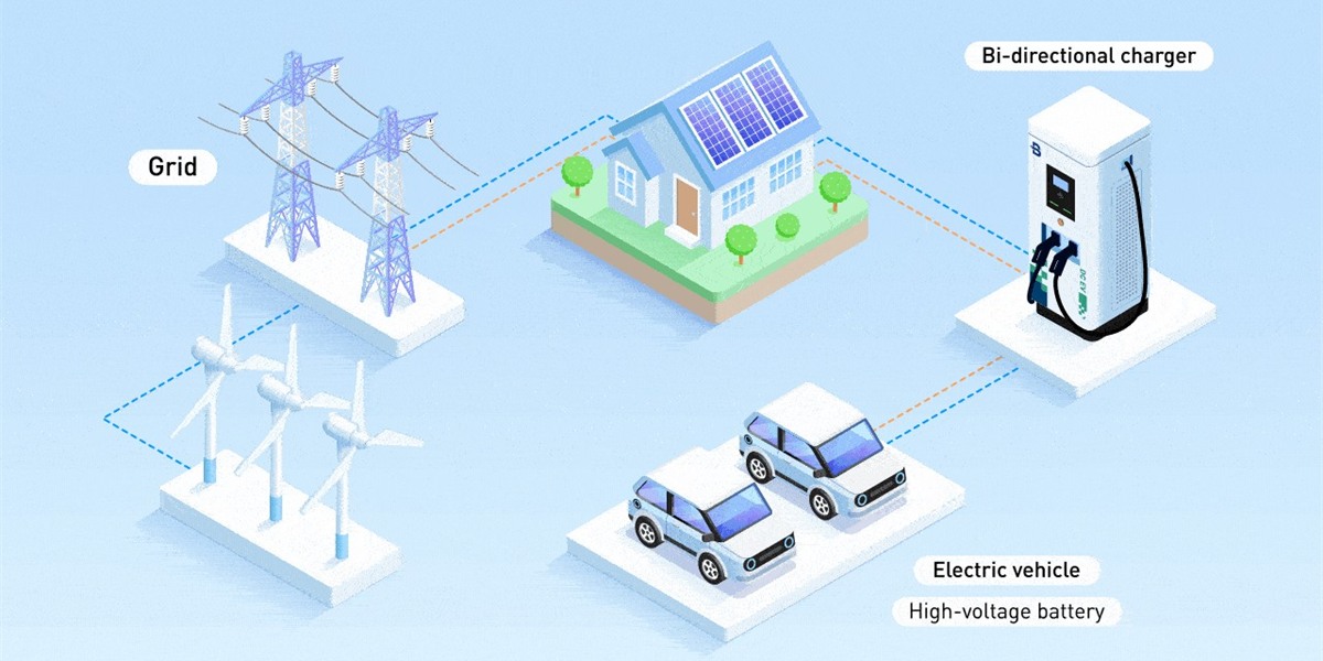
BESS-supported architecture breaks this loop. The battery absorbs the difference between contracted grid capacity and instantaneous site demand. The grid connection shrinks to match average load; the battery covers the peaks.
The Blueprint: Architecture of a BESS-Supported 480kW Site
The reference design combines three elements:
1. Split DC charging system (480kW)
One or two liquid-cooled power cabinets house hot-swappable 40kW/60kW liquid-cooling power modules, with dispensers deployed up to 100+ meters away. The 480kW ultra-fast liquid-cooled DC charging station for motorways is the reference implementation: separated power conversion and dispensers, 150–1000V wide output, and sustained high-current capability.
2. Site-level BESS (250–500kWh)
LFP battery racks coupled at the DC bus of the power cabinet (DC-coupled) or via a bi-directional PCS (AC-coupled). DC coupling avoids one conversion stage and lifts round-trip efficiency to ~93%.
3. EMS site controller
The software brain running OCPP 2.0.1 smart charging profiles. It forecasts session demand, manages battery SoC, enforces the grid contract (never exceeding the feeder limit), and executes peak shaving. The 360kW liquid-cooled charging station with RFID, OCPP, and POS demonstrates MIDA’s control-plane maturity: protocol-complete, payment-ready, and storage-integration-ready.
Sizing the Battery: The 5-Step Method
- Define the session profile: number of stalls, expected sessions/day, and peak coincidence (how often multiple stalls draw full power).
- Set the grid contract: target 30–50% of installed charging power (e.g., 150–250kW for a 480kW site).
- Calculate the peak gap: worst-case simultaneous demand minus grid contract = the energy the battery must cover per event.
- Size the battery: 1.5–2x the largest single peak event to preserve cycle life (e.g., a 400kWh battery for a 250kW peak gap sustained for 90 minutes).
- Verify recharge: the battery must refill during off-peak hours within the contracted grid limit.
| Site Scenario | Charging Power | Grid Contract | Battery Size | Peak Coverage |
|---|---|---|---|---|
| Urban hub (4 stalls) | 240kW | 100kW | 150–200kWh | 2–3 simultaneous sessions |
| Motorway corridor (8 stalls) | 480kW | 200kW | 300–500kWh | 4–6 simultaneous sessions |
| Fleet depot + trucks | 480kW | 250kW | 400–600kWh | 3–4 truck sessions at 1000V |
[Image Placeholder: Content 1200*600, ~250KB — blueprint diagram of BESS-supported 480kW split charging site with grid, battery, power cabinets, and dispensers]
The Financial Case: Where the Savings Come From
1. Grid-connection CAPEX reduction. Requesting 200kW instead of 500kW typically halves connection costs — saving $50,000–$250,000, which frequently covers the entire BESS investment.
2. Demand-charge reduction. In California (SDG&E/PG&E commercial rates), demand charges run $15–$30 per kW-month. A 250kW shaved peak saves $45,000–$90,000 per year — enough to pay for a 400kWh battery in 4–6 years while the charger network itself remains profitable.
3. Energy arbitrage. With time-of-use spreads of $0.10–$0.25/kWh in 2026 European and US markets, charging the battery at night and discharging into sessions at peak retail time adds $15,000–$40,000 per site-year.
4. Revenue stacking. The same battery can participate in frequency regulation or demand response where markets exist, adding $10,000–$30,000 per year without affecting the charging operation.
Capex Comparison: Grid-Fed vs BESS-Supported (480kW, 8-Stall Site)
| Line Item | Grid-Fed (500kW) | BESS-Supported (200kW + 400kWh) |
|---|---|---|
| Grid connection / transformer | $120,000–$250,000 | $40,000–$80,000 |
| Charging hardware (480kW split) | $110,000 | $110,000 |
| BESS (400kWh, installed) | — | $120,000–$160,000 |
| Civil works & permitting | $60,000–$120,000 | $30,000–$60,000 |
| Total CAPEX | $290,000–$480,000 | $300,000–$410,000 |
| Monthly demand charge (est.) | $7,500–$15,000 | $3,000–$6,000 |
| Time to live | 12–24 months | 3–6 months |
The message is unambiguous: for sites with constrained or expensive grid access, the BESS-supported path reaches revenue earlier, with comparable or lower total CAPEX and materially lower operating cost.
Deployment Roadmap: Phased, Funded, Reversible
The blueprint is designed to be deployed in funded milestones rather than a single risky bet:
- Phase 1 (Month 0–3): Install 240kW split charging on the available grid feed with the DC bus and controller provisioned for storage. Open for business. Revenue starts immediately.
- Phase 2 (Month 3–6): Add the BESS (150–300kWh) and activate peak-shaving logic. Demand charges drop; the site can now serve larger session spikes.
- Phase 3 (Month 6–12): Add a second cabinet and more dispensers to reach 480kW, using accumulated revenue and the freed grid headroom the battery created. Add arbitrage and grid-service programs.
Each phase is reversible and independently bankable — if traffic is slower than forecast, the operator simply delays the next phase instead of carrying idle capacity. This is the operational essence of MIDA’s modular design philosophy: one commercial DC fast charging portfolio spanning modules, cabinets, dispensers, and storage, so expansion is a procurement decision rather than a re-engineering project.
Operational Considerations for Constrained Sites
- Contracted-power enforcement: the EMS must hard-limit site draw to the grid contract even when the battery is empty — a “never trip the breaker” rule. MIDA’s site controllers enforce this at the cabinet level with millisecond response.
- Battery thermal management: liquid-cooled battery racks are mandatory for high-power corridor sites to prevent derating during back-to-back peak events in summer heat.
- Availability engineering: with the battery covering peaks, module failure cannot be allowed to idle the site — hot-swappable modules and N+1 spares keep availability above 98%.
- Telemetry and remote ops: OCPP 2.0.1 device models expose battery SoC/SoH and session data to the CSMS, enabling remote dispatch and proactive maintenance across a distributed network.
FAQ
1. How much grid capacity do I actually need for a 480kW station?
With a properly sized BESS, a 150–250kW grid feed suffices for typical four-to-eight stall patterns. The exact figure depends on session coincidence, but the 30–50% rule is a reliable planning starting point.
2. What happens if the battery is depleted during a peak rush?
The EMS sheds load gracefully: sessions continue at reduced power rather than tripping the grid breaker. Smart charging profiles queue vehicles so the highest-priority session keeps full power.
3. Can I add the battery later if I build the charger first?
Yes — if the site is designed with a provisioned DC bus, controller headroom, and physical space. This is exactly the staged-upgrade path the blueprint assumes.
4. Does the BESS reduce charger availability?
No — it increases it. The battery covers peaks that would otherwise overload the grid feed, and module-level redundancy means a single module failure costs 40–60kW of capacity, not the whole site.
5. Which battery chemistry is best for charging sites?
LFP (LiFePO4) is the 2026 default: 6,000+ cycles, excellent thermal stability, no cobalt, and strong fire-safety profiles that simplify permitting under NFPA 855.
6. How long does the BESS take to pay back?
In high-demand-charge markets (California, Germany, UK), demand-charge savings alone pay for the battery in 4–6 years; arbitrage and grid services shorten this to 3–5 years.
7. Is this architecture compliant with utility interconnection rules?
Yes. The EMS enforces a firm power limit at the point of common coupling, which most utilities treat as equivalent to a smaller connection — and it enables demand-response programs that utilities actively reward.
Conclusion
Grid constraints should no longer dictate the pace or shape of ultra-fast charging rollouts. The BESS-supported 480kW split charging blueprint delivers the same driver experience as a fully grid-fed site — four to eight stalls of 480kW-class charging — on a fraction of the grid connection, at lower total CAPEX in constrained locations, and on timelines measured in months rather than years. The architecture is modular, phased, and reversible, built on standardized liquid-cooled power modules and a protocol-complete control plane. For CPOs facing utility dead ends, the blueprint is not a workaround — it is the new standard way to build.
Post time: Aug-24-2026


