
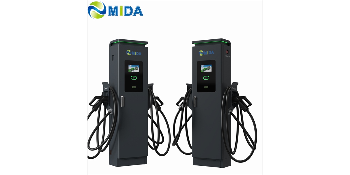
Split DC Charger vs All-in-One: Which Architecture Fits Your EV Charging Hub?
Quick Answer
A split DC charger separates the rectifier/power conversion cabinet from the user-facing charging terminals, distributing DC power over a controlled bus to multiple dispensers. An all-in-one charger integrates rectifiers, control electronics, and the charging cable into a single pedestal. Split architecture typically wins for hubs above 240–360 kW, fleet depots, and space-constrained urban sites where redundancy, cable reach, and serviceability matter. All-in-one units remain the pragmatic choice for single-stall, low-power deployments (60–180 kW) with simple permitting and immediate plug-and-play installation. The correct decision hinges on five variables: total hub power, stall count, available footprint, uptime requirement, and your five-year service model — not on headline kW alone.
Key Takeaways
- Split architecture decouples power from packaging. One power cabinet can feed 4–8 dispensers, so total hub capacity scales without duplicating rectifier hardware at every stall.
- Redundancy is structural, not optional. Because rectifier modules are pooled in a shared cabinet, a single module failure degrades output rather than taking an entire stall offline.
- Space efficiency favors split systems in dense sites. Removing heavy power electronics from the parking bay releases roughly 40–60% of the footprint per stall and eliminates the need for a reinforced concrete pad at every post.
- Maintenance economics shift to the cabinet. Field service concentrates on one accessible power unit instead of multiple sealed pedestals, cutting truck rolls and mean time to repair.
- All-in-one still fits. For single-stall retail, small commercial parking, or phased pilots, integrated units reduce civil works, cabling, and commissioning complexity.
Why the Architecture Question Arrives So Late in Most Projects
Most charging hub procurement conversations begin with power rating and connector type. They should begin with architecture. The physical arrangement of power conversion determines civil works, cable routing, service access, expansion headroom, and — critically — the cost curve of the hub over a ten-year horizon.
A site host evaluating a 600 kW hub has fundamentally different constraints than a hotel adding two 22 kW wallboxes. Yet both are frequently quoted the same all-in-one pedestal approach simply because it is the default SKU in the market. Understanding the structural difference between split and integrated architectures is the fastest way to avoid over-capitalizing a site — or under-building one that must later be torn up.
What “Split” and “All-in-One” Actually Mean
The All-in-One Pedestal
An all-in-one DC charger contains the AC-to-DC rectifier modules, the DC bus, the controller, the metering, the safety interlocks, and the output cable within one enclosure. Power enters at the base, typically from a local AC distribution board, and DC exits a few meters away at the connector.
The design is elegant in its simplicity: fewer interfaces, fewer drawings, fewer failure domains to diagnose. Its constraint is physical. Every kilowatt of rectification requires volume for magnetics, heatsinks, fans or cold plates, and thermal clearance. Push past roughly 200–240 kW and the pedestal grows both heavier and larger, often requiring a deeper excavation, a larger concrete pad, and a service corridor that reduces net parking yield.
The Split Architecture
A split-type DC charging station divides the system into a power cabinet (sometimes called a power unit or rectifier cabinet) and one or more charging terminals or dispensers. The cabinet houses the AC input protection, the rectifier modules, the DC busbar, the cooling system, and the central controller. The dispensers house the user interface, the connector, the cable management system, and the safety and communication electronics.
DC power travels from the cabinet to each dispenser over a low-loss DC distribution run. Because DC conductor sizing depends on current and voltage rather than on conversion hardware, the cabinet can sit 20–80 meters away — a distance that would be impractical for an AC feed of comparable power due to voltage drop and cable cross-section.
This separation creates three structural advantages that no amount of all-in-one engineering can replicate: pooled power, remote placement, and centralized service.
The Engineering Trade-offs That Actually Matter
1. Power Pooling and Dynamic Allocation
In a split system, the rectifier capacity of the cabinet is a shared resource. A 480 kW cabinet feeding six dispensers can allocate power dynamically — for example, delivering 240 kW to a single vehicle that can accept it while the remaining stalls operate at 40 kW each. As vehicles taper, capacity reflows.
An all-in-one hub achieves the same outcome only by installing six separate 480 kW-capable units, which means paying for six full rectifier stacks that are almost never fully utilized simultaneously. For a hub with an average concurrency of 40–60%, that is significant stranded capital.
2. Thermal Management and Derating
High-power DC charging generates substantial heat. In an all-in-one unit, that heat is released directly into the parking environment, often adjacent to the vehicle. In a split system, the cabinet can be placed in a shaded, ventilated equipment zone or an enclosure with dedicated airflow, allowing larger heatsinks, higher module density, and more effective liquid cooling.
This matters for derating behavior. Liquid-cooled power cabinets routinely maintain full rated output at 50 °C ambient, while air-cooled integrated pedestals commonly derate above 40–45 °C. On a hot summer afternoon at a highway hub, that difference determines whether a customer receives 250 kW or 120 kW.
3. Cable Management and Stall Geometry
Split architecture frees the dispenser from carrying power electronics, which means the post can be slim, low-profile, and positioned for optimal cable reach. This enables configurations that are physically impossible with integrated units: back-to-back dispensers on a single island, overhead cable management for heavy-duty connectors, and layouts that preserve drive-through lanes for buses and trucks.
For fleets operating vehicles with 3–5 meter charging port offsets, dispenser placement flexibility is not a convenience — it is a safety and throughput requirement.
4. Failure Domains and Uptime
An all-in-one unit is a single point of failure for its stall. If the rectifier fails, the stall is offline until a technician with the correct module arrives and performs the replacement in situ, often in a public parking area.
In a split system with N+1 or N+2 rectifier redundancy, module failure triggers a capacity reduction, not an outage. The cabinet remains operational, the dispensers keep serving vehicles at reduced aggregate power, and the module swap happens during a scheduled visit.
5. Installation and Civil Works
All-in-one units require AC power, data, and a foundation at every stall. Split systems require one substantial AC feed and one foundation at the cabinet, plus a lightweight anchor for each dispenser. In a 12-stall hub, that difference can eliminate ten separate power trenches, substantial trenching rework, and the associated permitting inspections.
For a comparison of how MIDA structures these deployments across project sizes, the EV charging solutions portfolio outlines the cabinet-to-terminal combinations available.
Architecture Comparison at a Glance
| Parameter | All-in-One DC Charger | Split-Type DC Charging Station |
|---|---|---|
| Typical single-unit power | 60 kW – 240 kW | Power cabinet 240 kW – 720 kW+ |
| Dispensers served | 1 | 2 – 8 (typical), expandable |
| Footprint per stall | 1.2 – 2.0 m² (pedestal + service clearance) | 0.4 – 0.8 m² per dispenser |
| Rectifier redundancy | None or limited internal N+1 | Pooled N+1 / N+2 across cabinet |
| Cooling | Air-cooled (mostly) | Air or liquid-cooled cabinet |
| Distance power-to-stall | 3 – 6 m (integral cable) | 20 – 80 m DC distribution run |
| Civil works | AC feed + foundation per stall | Single AC feed + one foundation |
| Service access | In-bay, weather-exposed | Cabinet in equipment zone, controlled |
| Best fit | 1–2 stall sites, ≤ 240 kW | Hubs ≥ 300 kW, depots, fleets, urban clusters |
| Expansion model | Add another pedestal | Add a dispenser to the existing cabinet |
Where Split Architecture Is the Clear Default
Fleet depots and logistics yards. Overnight and opportunity charging for delivery vans, light trucks, and buses demands many stalls with high concurrency. A split system with 360–480 kW of cabinet capacity serving six to eight dispensers matches the depot’s actual power availability while keeping capital aligned to charger count.
Highway and corridor hubs. Sites with limited grid capacity benefit most from pooling, because the hub can present a lower coincident demand than the sum of individual stall ratings. MIDA’s 600 kW–720 kW liquid-cooled DC charging station is designed for exactly this corridor and heavy-vehicle use case, where a single power cabinet supports multiple high-power dispensers with heavy-duty cable management.
Dense urban and mixed-use parking. Structural load limits, ceiling heights, and aisle widths make integrated pedestals awkward. Slim dispensers positioned along walls or columns, with the cabinet in a basement plant room, resolve both spatial and vibration constraints.
Sites planned for phased build-out. Buying one 480 kW cabinet and four dispensers now, then adding dispensers as utilization grows, converts a large capital event into a staged investment while preserving the grid connection.
Solar and storage integrated hubs. Where DC-coupled battery storage is part of the design, the split topology allows the power cabinet to draw from both grid and battery on a shared DC bus — a configuration described in MIDA’s 200 kWh solar BESS EV charging station reference. This coupling is difficult to achieve with independent all-in-one pedestals.
Where All-in-One Remains the Right Answer
Integrated pedestals are not obsolete. They are simply mismatched to certain problems. Choose all-in-one when:
- The site hosts one or two stalls and the total installed power is below 240 kW.
- Grid capacity is already sufficient and no future expansion is contemplated.
- Civil works are constrained by cost, timeline, or landlord restrictions.
- The site is a franchise model where each operator maintains its own unit independently.
- Deployment speed outweighs long-run unit economics — a pilot, an event, or a temporary installation.
The failure pattern to avoid is using all-in-one units to build a large hub by accumulation. Twelve pedestals is not a hub; it is twelve independent projects sharing a parking lot, with twelve service contracts, twelve failure domains, and no power sharing.
A Decision Framework You Can Apply in One Meeting
- Count the stalls and the concurrency. If peak simultaneous charging exceeds three vehicles, evaluate split.
- Calculate the coincident demand. Compare the sum of stall ratings against actual grid capacity. If the sum exceeds capacity, pooling is mandatory.
- Audit the footprint. Measure available equipment space outside the parking bays. A cabinet needs 1.5–3 m² with clearance; dispensers need very little.
- Model the five-year utilization curve. If utilization is expected to grow beyond 30%, design for expansion via dispensers rather than additional pedestals.
- Define the uptime requirement in the SLA. If the contract specifies 98%+ availability, redundancy in a pooled cabinet is the only economical route.
- Price the full lifecycle, not the bill of materials. Include trenching, foundations, service visits, spares inventory, and expected module replacement intervals.
Cost and TCO Considerations
Capital cost per stall favors split systems above roughly six stalls. The cabinet’s rectifier capacity is amortized across all dispensers, and the marginal cost of an additional stall becomes a dispenser plus a DC run rather than a full charging unit.
Operational cost favors split systems more decisively. Service labor is the dominant recurring expense in DC charging. A single cabinet service visit can address multiple stalls, whereas integrated pedestals require one visit per unit — and often a second visit if the fault is module-level. Over a ten-year horizon with typical urban truck-roll costs, consolidating 12 service points into 2 materially changes the TCO model.
Energy cost is often overlooked. Pooled power with dynamic allocation reduces the likelihood of simultaneous high-power sessions that spike site demand charges. A split system that can throttle or sequence dispensers according to a site-level power ceiling provides a direct, measurable reduction in monthly demand charges.
Compliance, Standards, and Interoperability
Both architectures must satisfy the same functional standards: IEC 61851 and IEC 62196 for AC/DC charging and connectors, OCPP 1.6J or 2.0.1 for back-end communication, and regional requirements such as CE and TÜV marking in Europe or UL certification in North America. The split architecture adds one consideration: the DC distribution segment between cabinet and dispenser must meet applicable insulation, protection, and isolation requirements, which reputable manufacturers address through factory-terminated, tested cabling and documented isolation monitoring.
Specify the following regardless of architecture: protection degree (IP54 minimum for outdoor, IP65 for exposed coastal or dusty sites), touch-safe connector design, integrated RCD/insulation monitoring, surge protection at the AC input, and firmware update capability without physical intervention.
Bottom Line
Choose all-in-one when the problem is one or two stalls and the constraint is simplicity. Choose split when the problem is a hub — where power must be shared, space is scarce, uptime is contractual, and growth is expected. The architecture decision is a ten-year decision disguised as a hardware choice, and it is best made before the civil drawings are finalized.
FAQ
What is a split-type DC charging station?
A split-type DC charging station separates the power conversion cabinet from the charging dispensers. The cabinet contains rectifier modules and the DC bus; the dispensers contain the connector, user interface, and safety electronics. DC power is distributed from the cabinet to each dispenser over a controlled DC run.
Is a split DC charger more expensive than an all-in-one unit?
Per stall, no — above roughly six stalls. The cabinet’s cost is shared across multiple dispensers, so each additional stall requires only a dispenser and a DC distribution run. For one or two stalls, all-in-one is usually cheaper on day one.
How far can the power cabinet be from the dispensers?
Typical supported distances range from 20 to 80 meters, depending on output current, conductor sizing, and acceptable voltage drop. Manufacturers specify maximum DC run length per configuration, and exceeding it requires recalculating conductor cross-section.
What happens if one rectifier module fails in a split system?
The cabinet continues operating at reduced aggregate capacity if it has N+1 redundancy. Vehicles continue to charge, though simultaneous high-power sessions may be throttled. The failed module is replaced during a scheduled service visit rather than causing a stall outage.
Can a split system be expanded later?
Yes, and this is one of its primary advantages. Additional dispensers can be connected to the existing cabinet if spare DC outputs and rectifier capacity are available. This makes phased build-out practical without renegotiating the grid connection.
Do split DC systems support battery storage and solar integration?
They can, and the pairing is increasingly common. A DC bus in the power cabinet allows grid and battery inputs to be combined efficiently, which is why solar-plus-storage hubs frequently specify split architecture with high-efficiency charging modules.
Which architecture is better for high-ambient-temperature sites?
Split systems generally perform better. Locating the electronics in a dedicated, ventilated cabinet with liquid cooling allows full-rated output at higher ambient temperatures, whereas integrated air-cooled pedestals typically derate earlier.
Conclusion
The split versus all-in-one decision is not a matter of which technology is newer. It is a matter of which constraint dominates the project: simplicity or scalability. Sites that will grow, share power, and answer to an uptime SLA are structurally better served by a power cabinet with distributed dispensers. Sites that need two stalls and a fast installation are better served by an integrated pedestal. Map your stall count, grid capacity, footprint, and service model against the framework above, and the architecture selects itself.
Post time: Sep-16-2026


