
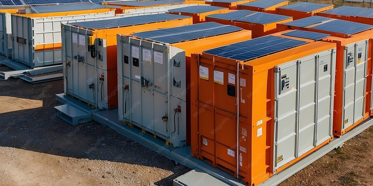
Designing Mega-Watt Split DC Charging Systems for Heavy-Duty Fleet Electrification
Quick Answer
Mega-watt split DC charging systems separate the high-power conversion hardware from the vehicle-side dispenser, letting a fleet depot concentrate 1–3.75MW of charging power in a central cabinet room and feed 8–20 lightweight liquid-cooled dispensers at the parking bays. This architecture is the only practical way to electrify heavy-duty fleets: a Class 8 e-truck with a 500–800kWh battery needs 300–500kWh of energy in a 45–90 minute rest or turnaround window, which demands 300–480kW sustained per vehicle and multi-megawatt site capacity. Split systems deliver that power with N+X module redundancy, hot-swappable service, and modular 240kW cabinets that scale from pilot to full yard without re-engineering. They are also the natural stepping stone to the Megawatt Charging System (MCS) standard that will define truck charging from 2027 onward.
Key Takeaways
- Multi-MW capability with a realistic grid footprint: A 2.4MW split system can serve 6–10 trucks simultaneously while centralizing demand management behind one connection point.
- Redundancy is engineered, not optional: N+X power-module redundancy plus hot-swap design holds 99%+ charging availability — critical when an idled truck costs carriers $800–$1,500 per day.
- Liquid-cooled 600A+ dispensers keep cables manageable: High current at the bay requires liquid cooling; a 600A cable is 30–50% lighter than the air-cooled equivalent and safe for repeated daily handling.
- Modular growth protects capital: Adding a 240kW cabinet grows site capacity in defined steps, matching fleet growth instead of betting on full build-out on day one.
- MCS-ready by design: A 1000V split platform with liquid-cooled high-current dispensers upgrades to MCS connectors without replacing the power architecture.
Why Heavy-Duty Electrification Forces a New Architecture
Heavy-duty fleet electrification is a different engineering problem from passenger-car charging. The numbers decide the design:
- A Class 8 e-truck battery is 400–800kWh — 8–16× a passenger EV pack.
- Depot dwell windows are 45–90 minutes between shifts or during mandated rest breaks.
- Replenishing 300–500kWh in 60–90 minutes requires 300–480kW sustained per vehicle — and a yard of 10 trucks at 2,000km/week needs 1.5–3.5MW of site capacity.
- High-power sessions run 6–20 hours per day, so thermal design, reliability, and serviceability dominate total cost of ownership.
Integrated all-in-one chargers cannot scale to this regime economically: each bay would need its own large cabinet, its own HVAC, its own service access, and its own civil works. The split architecture inverts the model — one central power room, many slim dispensers — which is why every serious depot design in 2026 converges on it.
The power cabinet room becomes the “energy heart” of the depot, while drivers interact only with lightweight dispensers at the bay — no high-voltage hardware, no fan noise, no heat in the yard.
The Split DC Architecture, Defined
A split DC charging system has two physical halves:
- Power cabinet (power conversion unit): houses the AC/DC rectifier modules, control electronics, and cooling. It converts grid AC to regulated DC and dynamically allocates power to dispensers. A 1MW+ system is built from paralleled 240kW cabinets using liquid-cooling power modules.
- Dispenser (charging terminal): a compact kiosk with the DC cable, connector, metering, and user interface. It contains no large power electronics, so it is small, quiet, and cheap to install and maintain.
Power flows from cabinet to dispenser over a shared DC bus — liquid-cooled for currents above 500A — so any cabinet can feed any dispenser, and the EMS can shift power dynamically between trucks as their charge curves demand.
Sizing a Mega-Watt Depot: A Worked Example
| Design Parameter | 2.4MW Depot (6 lanes) | 3.75MW Hub (10 lanes) | 1.2MW Pilot (3 lanes) |
|---|---|---|---|
| Power cabinets | 10 × 240kW | 16 × 240kW | 5 × 240kW |
| Dispensers (liquid-cooled) | 6 | 10 | 3 |
| Avg. per-lane power | 400kW | 375kW | 400kW |
| Grid connection | ~2.6MVA | ~4.1MVA | ~1.3MVA |
| Energy in 60-min window | ~2.0MWh | ~3.2MWh | ~1.0MWh |
| Typical fleet served | 15–25 e-trucks (overnight + opportunity) | 25–40 e-trucks | 6–10 e-trucks |
| Service model | Central power room, hot-swap modules | Central power room + spare modules on site | Central power room, one rack of spares |
The design rule: total cabinet power must exceed peak simultaneous demand, and the grid connection must cover the average energy draw (typically 50–65% of peak due to staggered arrivals and load management). A BESS-integrated version can cut the grid connection by another 30–50% while adding outage resilience.
Designing for Availability: The N+X Principle
A depot charger failure is not a nuisance — it is a missed route. The split architecture makes availability a design parameter:
- N+X module redundancy: Each 240kW cabinet runs 6 × 40kW or 4 × 60kW modules with one spare (N+1). If a module fails, the cabinet delivers 240kW from the spare without interruption, and the failed module is swapped hot in under 10 minutes.
- Cross-cabinet failover: Because all cabinets feed a common DC bus, a full cabinet failure is absorbed by the remaining cabinets at reduced per-lane power — the site degrades gracefully instead of losing a lane.
- Centralized spares: One service point holds all spares and test gear, so a 12-module site carries 2–3 spare modules instead of 12 spare stations.
- Remote diagnostics via OCPP 2.0.1: The EMS sees module-level telemetry (temperature, efficiency, cycle count) and can pre-empt failures before they become outages.
The MCS Trajectory: Future-Proofing the Power Architecture
The global trucking industry is converging on Megawatt Charging System (MCS) — up to 3.75MW per connection at 1250V DC — driven by the EU’s AFIR regulation and the CharIN MCS specification. The crucial insight for fleet buyers: MCS changes the connector and the high-current bus, not the power electronics or the cooling philosophy. A split system built today on 1000V liquid-cooled 240kW cabinets is already 80% of an MCS site. Upgrading means:
- Replacing dispensers and high-current cables with MCS-rated components.
- Adding high-voltage (1250V) power modules or a step-up converter in the power room.
- Extending the DC bus and grid connection per MCS power levels.
The power cabinets, thermal management, EMS, redundancy architecture, and civil works all carry forward. That is why the 480kW ultra-fast liquid-cooled DC charging station family and its split variants are engineered as the building blocks of the MCS era rather than a stopgap.
Deployment Sequence for a Fleet Depot
- Energy audit and duty-cycle analysis — collect route lengths, dwell windows, and fleet growth curves; this determines MW, MWh, and lane count.
- Grid application in parallel with design — utilities quote 12–24 months for multi-MVA connections, so the application starts on day one.
- Power room and civil works — transformer, switchgear, cabinet room, and cable trenches; dispensers need only bollards and a pad.
- Install and commission — cabinets, DC bus, dispensers, EMS, and OCPP 2.0.1 integration with the depot’s telematics and charging management platform.
- Phase to growth — start with 5 cabinets and 3 lanes; add cabinets and dispensers as fleet counts rise, with zero disruption to running lanes.
FAQ
1. What is the difference between split DC and integrated chargers for fleets? Split systems centralize power electronics in a cabinet room and feed slim dispensers at the bays. Integrated chargers combine both in one enclosure per bay. For depots above ~600kW, split wins on service, thermal management, cable ergonomics, and expansion cost.
2. How much grid power does a mega-watt depot need? Peak demand equals installed cabinet power (e.g., 2.4MW), but with load management and staggered arrivals the actual connection can be sized at 50–65% of peak — lower with BESS buffering. The utility application should start 12–24 months before target go-live.
3. Can one power cabinet feed multiple dispensers? Yes. A 240kW cabinet can feed 2–4 dispensers with dynamic power sharing — e.g., 120kW to two trucks, or all 240kW to one. The EMS reallocates power in real time as trucks complete.
4. How long does it take to charge a Class 8 e-truck? At 400kW average, a 600kWh battery gains ~40% SoC (240kWh) in 60 minutes — matching typical rest breaks. Full 10–80% sessions run 75–110 minutes depending on the truck’s charge curve.
5. Is liquid cooling necessary for megawatt charging? Yes, at currents above 500A. Liquid-cooled cables are 30–50% lighter, hold connector temperatures below 60°C, and survive the daily handling of yard staff. Air-cooled high-current cables become unmanageably heavy and derate in hot weather.
6. What happens when a module or cabinet fails? N+X redundancy means the site keeps charging: a spare module takes over instantly, and failed modules are hot-swapped in under 10 minutes. Full-cabinet failure triggers cross-cabinet power sharing, so no lane goes dark.
7. Will this system be compatible with MCS trucks in 2027+? Yes, by design. The 1000V liquid-cooled split platform upgrades to MCS with new dispensers, high-current bus, and 1250V power stages — the cabinets, cooling, EMS, and civil works carry forward.
Conclusion
Mega-watt split DC charging is the defining infrastructure decision of fleet electrification. It converts a depot’s grid capacity into usable truck-charging throughput with centralized service, engineered redundancy, and modular growth — while leaving a clean upgrade path to MCS. Fleet operators who standardize on split architecture today, with EV charging solutions built on liquid-cooled 240kW cabinets, are not buying a 2026 product; they are buying the foundation of their 2030 energy infrastructure.
MIDA Power designs and manufactures split DC charging systems, liquid-cooled power modules, and integrated storage solutions for freight, logistics, and public corridor operators. For depot design support and site sizing, contact MIDA via midapower.com, or explore the 360kW liquid-cooled charging station family for mid-scale fleet applications.
Post time: Aug-24-2026


