
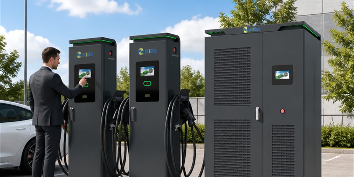
Installation Flexibility: Why Split Type 480kW DC Fast Chargers are Ideal for Urban Hubs
Quick Answer
Split type 480kW DC fast chargers are ideal for urban hubs because they physically separate the heavy power-conversion equipment from the driver-facing dispensers, solving the three constraints that dominate city installations: space, noise, and permit complexity. The power cabinet — housing AC/DC modules, cooling, and service points — can be installed in a basement electrical room, a service alcove, or a parking-garage plant area, while only a slim, quiet dispenser occupies the parking bay. This shrinks the footprint per charging point to under one square meter, keeps noise at the bay below 45 dB(A), and concentrates electrical work in one code-compliant location. For fleet yards, underground car parks, curbside hubs, and retail car parks, a 480kW split system delivers 4–8 high-power connectors from a single grid connection — with simpler permitting, faster civil works, and lower lifetime cost than the same capacity built from integrated all-in-one stations. Installation flexibility is the decisive commercial advantage of split architecture in dense urban environments.
Key Takeaways
- Split architecture reduces per-bay footprint to under 1 m² and allows the power room to be located up to 50m+ from the parking positions.
- Noise at the dispenser is below 45 dB(A) — compliant with most urban night-charging ordinances without acoustic enclosures.
- Liquid-cooled 600A cables keep dispensers compact and light, enabling installation against walls, columns, and in tight bays.
- Centralized power rooms simplify electrical inspection, permitting, and grid connection by consolidating switchgear and metering in one location.
- The same 480kW split system scales from a 4-connector retail pilot to a 16-connector fleet hub by adding cabinets — protecting the initial investment.
The Urban Installation Problem
Urban charging sites fail on details that rural and motorway sites never encounter. The parking bay is 2.5 meters wide with a column on one side. The landlord restricts where electrical equipment can be mounted. The neighborhood association has noise limits after 10 p.m. The fire department requires specific clearances around high-voltage cabinets. And the utility inspects everything before energizing.
Integrated all-in-one DC fast chargers fight these constraints. A 480kW integrated unit is a large, heavy, fan-cooled cabinet at the bay: it consumes 2–4 m² of parking-adjacent space, emits 60–70 dB(A) of cooling noise, requires clearance for airflow and service access, and forces the utility connection, metering, and protection into a piece of equipment sitting in the middle of the parking area.
The split architecture inverts this design. The equipment that generates heat and noise moves away from the driver; the equipment the driver touches becomes as small as a parking meter. Every urban constraint is addressed at the source rather than patched around.
Split vs. Integrated: The Urban Site Comparison
| Site Constraint | Integrated 480kW Unit | Split Type 480kW System |
|---|---|---|
| Footprint at parking bay | 1.5–3 m² per station, clearance required | <1 m² dispenser, wall or column mountable |
| Power room requirement | None — equipment at bay | 4–6 m² electrical room, flexible location |
| Noise at bay | 60–70 dB(A) fans | <45 dB(A), typically below ordinance limits |
| Heat rejection | At bay, into parking area | At power room, into plant/ventilated space |
| Service access | Requires bay clearance, lane closure | Single service point in power room |
| Grid connection | Distributed, multiple cable runs | Consolidated switchgear and metering |
| Civil works | Multiple pads, conduits, ventilation | One room + lightweight dispenser mounts |
| Security of equipment | Exposed to weather, vandalism | Protected indoor location |
Where the Flexibility Pays: Four Urban Deployment Scenarios
1. Underground and multi-storey car parks
Multi-storey car parks are the highest-density urban charging real estate, but they punish integrated chargers: ceiling heights are limited, ventilation is poor, columns crowd the bays, and the structure is not designed for heavy equipment. A split system solves each problem. The power cabinets go into the ground-floor or basement plant room — often the only area with adequate electrical access and ventilation — while dispensers mount on columns or walls at each level. Liquid-cooled cables run through the structure, and because the dispensers are fanless and quiet, there is no additional ventilation requirement at the bays. The result: a 480kW, 6–8 connector installation in a car park where integrated units could not fit at all.
2. Curbside and on-street hubs
On-street charging is the most land-constrained segment. Pavement space is contested, and every square meter of equipment is a lost parking spot or a blocked sightline. Split architecture allows the power room to live inside a building — a shop basement, a garage, a building service room — with only a slim bollard-style dispenser on the street. Cable runs of 30–50 meters are routine with liquid-cooled DC cabling, which keeps voltage drop acceptable even at 480kW. Municipalities approve these installations faster because the street furniture is minimal and the electrical installation is fully inside a compliant building.
3. Retail car parks and commercial centers
Retail owners care about three things: customer experience, revenue per parking space, and capital efficiency. A 480kW split system preserves parking capacity (dispensers reclaim bay space versus station footprints), removes noise complaints from adjacent retail units, and lets the landlord phase capacity: install the power room and 2–4 dispensers first, add more as EV adoption grows. The centralized power room also makes the site future-ready for battery storage and solar integration, which retail owners increasingly bundle into their energy strategy.
4. Urban fleet depots (last-mile and ride-hail)
Last-mile delivery and ride-hail fleets operate from cramped inner-city depots where trucks must charge overnight and again between shifts. These depots rarely have floor space for large station cabinets. Split systems place the power electronics against a back wall or in a mezzanine room, leaving the entire yard surface for vehicles. The 480kW liquid-cooled ultra-fast charging station architecture — proven on motorway corridors — translates directly to depot yards, where multiple 240kW cabinets feed dispensers along the vehicle rows.
Liquid Cooling: The Enabler of Slim Dispensers
The flexibility of split architecture depends on one enabling technology: liquid cooling of the DC cables and connectors. Without it, a 480kW-rated cable would be a thick, stiff copper bundle that no driver can comfortably handle and no city planner wants to see on a sidewalk.
Liquid-cooled cable assemblies circulate coolant through the cable jacket, removing the heat that would otherwise require massive copper cross-sections. The practical benefits:
- Lighter cables: 600A liquid-cooled cables weigh roughly 30–50% less than their air-cooled equivalents, with a smaller bending radius.
- Smaller dispensers: The dispenser houses only the cable, connector, display, and metering — no large heat sinks or fans.
- Reliable high current: Sustained 600A output without thermal derating, which is essential for 800V trucks drawing 480kW+.
- Longer cable runs: Liquid cooling allows the power-to-dispenser distance to stretch tens of meters, which is what makes the “power room in the basement, dispensers on level 3″ layout physically possible.
Permitting, Electrical Inspection, and Grid Connection
Municipal approval is often the longest lead time in an urban project. Split architecture shortens it in four ways:
- One electrical installation point. All switchgear, metering, protection, and disconnection live in one room, making the electrical inspection a single visit rather than a tour of scattered cabinets.
- Familiar building services. The power room is treated like any plant room — standard ventilation, fire separation, and access requirements that inspectors already know.
- Reduced street furniture review. On-street deployments present only the dispenser for urban-design review; the heavy electrical equipment is out of public sight.
- Simplified utility application. The utility sees one consolidated load with one point of common coupling, simplifying connection agreements and export metering if solar or storage is added later.
| Permitting Factor | Integrated Units | Split System |
|---|---|---|
| Electrical inspections | One per station location | One consolidated power room |
| Noise compliance | Often requires acoustic measures | Dispensers inherently quiet |
| Street furniture approval | Large cabinets on public land | Minimal dispenser footprint |
| Fire/ventilation review | Per-unit clearances at bays | Standard plant-room requirements |
| Utility connection | Multiple connection points | Single point of common coupling |
Sizing and Phasing a 480kW Urban Hub
A 480kW split system typically comprises two 240kW power cabinets and four to eight dispensers. Phasing options give urban owners a pay-as-you-grow path:
- Phase 1 (pilot): One 240kW cabinet, 2–4 dispensers, 240kW of capacity. This is enough to validate demand, load profiles, and customer behavior with modest capital.
- Phase 2 (scale): Add a second 240kW cabinet and 2–4 more dispensers, reaching the full 480kW and up to 8 connectors — without touching the grid connection if it was sized for 480kW from the start.
- Phase 3 (harden): Add BESS and solar integration in the power room, converting the hub into a managed energy asset that shaves demand peaks.
The lesson for urban operators: size the civil works and grid connection for the final capacity, but buy the hardware in stages. Split architecture is the only popular form factor that supports this staging without abandoning equipment.
Why 480kW Is the Sweet Spot for Urban Sites
Higher headline power (960kW, 1440kW) is compelling for motorway and depot megasites, but urban hubs rarely need — or can legally obtain — that much capacity at one address. 480kW occupies the practical sweet spot:
| Urban Hub Type | Connectors | Typical Grid Need | Power Level |
|---|---|---|---|
| Retail car park | 4–6 | 400–500kVA | 480kW split |
| Underground car park | 6–8 | 400–500kVA | 480kW split |
| Curbside hub | 4 | 250–400kVA | 240–480kW split |
| Urban fleet depot | 8–16 | 500–800kVA | 480–960kW split |
At 480kW with four to eight connectors and dynamic load sharing, a hub delivers a 30–40 minute charging experience for the majority of urban EVs — enough throughput for the revenue model, with a grid application that most cities can approve within a single utility cycle.
MIDA’s Urban-Ready Split DC Solutions
MIDA Power designs split DC systems with urban deployment constraints as a primary input, not an afterthought. The company’s liquid-cooled ultra-360kW charging station with RFID, OCPP and POS demonstrates the full-service, attended-hub configuration for retail and depot environments where access control and payment matter. For higher-power urban corridors, the 480kW liquid-cooled ultra-fast charging station delivers the throughput that dense hubs require, built on the same 40kW/60kW liquid-cooling power modules that keep the power room compact and serviceable.
Every MIDA station ships with TUV/CE/UL certification, OCPP 1.6J/2.0.1 support for integration with city and operator management platforms, and the module-level telemetry that makes predictive maintenance possible in installations where service access is difficult. For site developers, landlords, and fleet operators planning urban charging, the commercial DC fast charging range offers the flexibility to match equipment to the site — not the site to the equipment.
FAQ
1. What does “split type” mean for a 480kW DC fast charger?
It means the power conversion equipment (power cabinet) is separated from the charging terminal (dispenser). The cabinet installs in a service room; the dispenser sits at the parking bay, connected by liquid-cooled DC cables.
2. How far can the power cabinet be from the dispensers?
With liquid-cooled DC cabling, runs of 30–50 meters are practical without significant voltage drop or derating. Some installations exceed 50m; the exact limit depends on cable specification and site design.
3. Is a split 480kW charger quieter than an integrated one?
Yes. The fans, pumps, and power electronics live in the power room; the dispenser is essentially silent (below 45 dB(A)). This matters for night charging in residential-adjacent and underground sites.
4. Do split systems require more total space than integrated chargers?
No — they require space in different places. The bay footprint shrinks dramatically (dispenser under 1 m²), while the power room occupies a flexible location (basement, plant room, alcove) where space is cheaper and easier to service.
5. Can a split 480kW system be installed in an underground car park with low ceilings?
Yes, and this is one of its best use cases. Dispensers mount on columns or walls, and the power cabinets go in the plant room or ground floor — no heavy equipment needs to be lowered into the parking levels.
6. What grid connection does a 480kW split system need?
Typically a 400–500kVA supply (400V or 480V three-phase), sized for the final site capacity. Metering, protection, and disconnection are consolidated in the power room, simplifying the utility application and inspection.
7. Can I start with less than 480kW and expand later?
Yes. Split systems are modular: start with one 240kW cabinet and add a second plus dispensers as demand grows. If the civil works and grid connection are sized for 480kW from the start, expansion is a hardware purchase, not a construction project.
Post time: Aug-21-2026


