
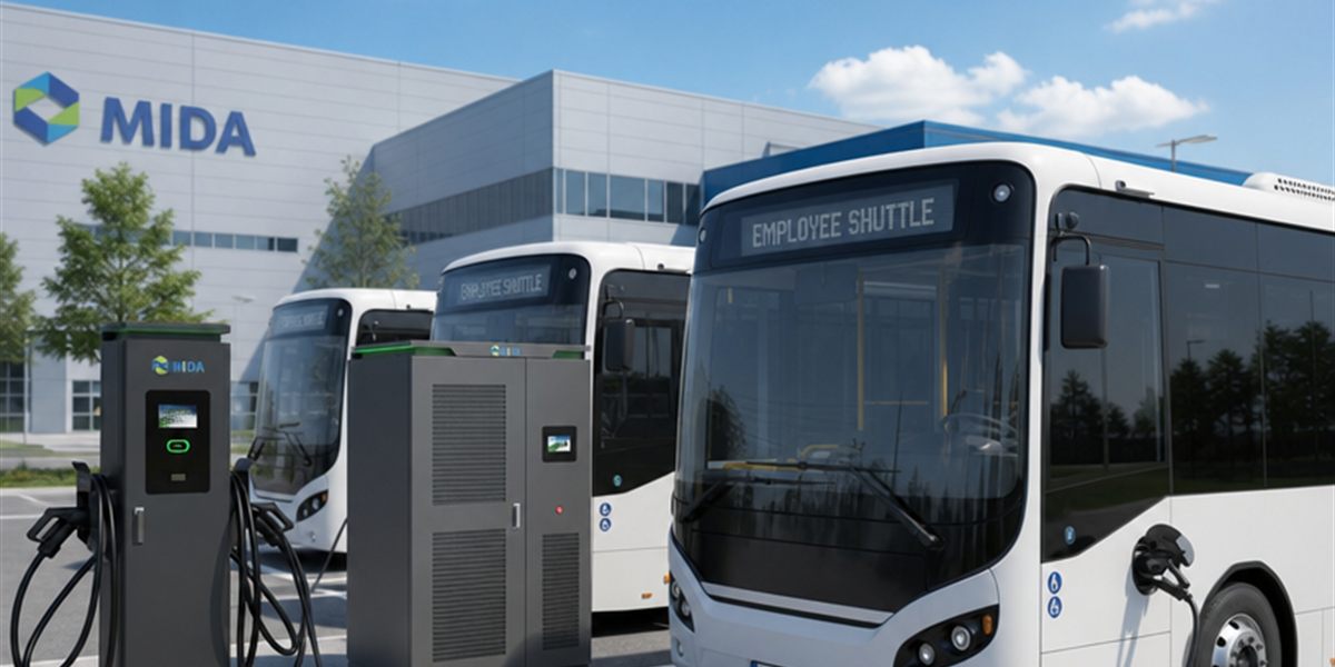
Smart Load Balancing in 1440kW Split DC Super Charging Systems for Busy Hubs
Quick Answer
Smart load balancing in a 1440kW split DC super charging system is the real-time allocation of DC power between multiple dispensers and power cabinets, governed by software rather than fixed hardware wiring. Instead of installing dedicated transformers and chargers sized for worst-case simultaneous demand, a 1440kW system serves 12–24 connectors with a pool of modular power that is redistributed every few seconds based on vehicle demand, battery acceptance, queue priority, and grid constraints. For busy hubs — truck stops, fleet depots, transit interchanges, and highway plazas — this converts a fixed 1440kW grid connection into flexible throughput: vans charge at 150kW, sedans at 250kW, and heavy trucks at 600kW+, all from the same cabinets. The measurable outcomes are higher utilization per kWh of grid capacity, 30–50% reductions in demand charges through peak shaving, and the ability to add connectors without adding grid capacity. Load balancing is not an optional software extra; it is the core engineering feature that makes megawatt-scale split DC charging economically viable in 2026.
Key Takeaways
- A 1440kW split system with dynamic load balancing can serve 12–24 connectors from one grid connection, matching power to vehicle demand in real time.
- Static allocation wastes capacity — dynamic balancing typically lifts average connector utilization by 20–40% compared with fixed power assignments.
- OCPP 2.0.1 smart-charging profiles give the site controller standardized control over power limits per connector, without vendor lock-in.
- Peak shaving with BESS integration can cut demand charges by 30–50%, often funding the control system within its first year.
- Modular 240kW cabinets mean load balancing scales in predictable steps — 480kW, 960kW, 1440kW — as hub traffic grows.
The Busy Hub Problem: Demand That Never Matches the Nameplate
Every charger manufacturer publishes a headline power figure. The uncomfortable truth of a busy charging hub is that nameplate power is almost never what a site delivers — because vehicles do not all arrive at the same state of charge, do not all accept the same power, and do not all stay the same duration. A hub with twelve connectors and a 1440kW connection could, in a naive fixed-power design, be forced to divide that power statically: six connectors at 240kW each, or twelve at 120kW. The first configuration wastes capacity when a van arrives needing only 100kW; the second makes every truck wait far longer than necessary.
The result is a site that is simultaneously under-utilized and congested. Utilization per connector drops, queue times rise, and the operator is paying demand charges for capacity that is idle half the day. Smart load balancing exists precisely to eliminate this mismatch.
How Smart Load Balancing Works in a Split DC System
In a split DC architecture, power is a shared pool. The 1440kW system is typically composed of six 240kW power cabinets, each containing liquid-cooled power modules. The dispensers are the customers of that pool — they request power, and a central controller (the site’s energy management or charging management system, CSMS) grants it.
The allocation logic is not a simple round-robin. Modern load balancing considers, typically on a 1–5 second cycle:
- Vehicle demand and battery acceptance. The charger reads the vehicle’s request via the charging session negotiation (ISO 15118 / DIN 70121 / CCS). A battery at 20% SoC accepts full power; the same battery at 85% tapers to a fraction. Allocating power to the battery that can actually absorb it is the single largest efficiency lever.
- Queue and priority rules. Fleet operators can prioritize departing trucks over discretionary passenger sessions; hub operators can reserve power for high-value customers or enforce fair-share policies.
- Grid and transformer limits. The controller never exceeds the site’s contracted capacity, transformer rating, or feeder ampacity. This is a hard safety constraint, not a soft preference.
- Energy price and demand-response signals. During peak tariff windows, the system can cap total site draw or shift load to battery storage; during demand-response events, it can curtail precisely as the utility requires.
The three allocation strategies in use across 2026 hubs illustrate the range of outcomes. A fixed/static split — twelve connectors at 120kW forever — typically yields 40–60% utilization, with long truck sessions and idle capacity overnight. Per-lane dynamic allocation, where power follows the vehicle’s request, lifts utilization to 65–80% but ignores queue priority. Full smart balancing — combining vehicle demand, queue priority, grid limits, and price signals — sustains 80–95% utilization while shaving peaks and cutting demand charges.
Power Sharing in Practice: The 1440kW Scenario Table
A concrete example makes the value concrete. Consider a motorway-adjacent hub in 2026 with a 1440kW split system, eight power cabinets worth of modules configured as six effective 240kW units, and sixteen CCS2 connectors across eight dual-cable dispensers. The hub is busy but not saturated — 14 vehicles connected at once:
| Connector Group | Vehicles Connected | Immediate Demand (kW) | Balanced Allocation (kW) | Charge Time Saved vs. Fixed 120kW |
|---|---|---|---|---|
| Truck bays (4 connectors) | 2 e-trucks at 15% SoC, 2 at 60% | 900 | 600 + 180 + 90 + 90 = 960 | ~35–40% shorter truck sessions |
| Passenger fast bays (6) | 6 EVs, mixed 20–70% SoC | 420 | 320 total (taper-aware) | ~15% shorter, no wasted power |
| Light-duty bays (4) | 4 vans, 30–50% SoC | 220 | 160 total | Adequate, no oversizing |
The same 1440kW grid connection delivers nearly the throughput of a naively “bigger” site because power flows where the batteries can accept it — and the controller keeps the site under its transformer limit even during a synchronized arrival peak.
Peak Shaving: Where Load Balancing Pays the Bills
For hub operators, the single largest controllable cost is often the utility demand charge — the fee for the highest 15-minute average draw in the billing month. A 1440kW site with poor power management can trigger demand charges on a handful of synchronized sessions that never repeat; a smart system prevents those spikes from ever occurring.
The 2026-standard configuration pairs load balancing with a behind-the-meter battery storage system:
- The CSMS forecasts site load for the next 15–60 minutes using session history, arrival patterns, and weather.
- When forecast demand would exceed the contracted peak, the controller instructs chargers to draw from the battery instead of the grid.
- The battery recharges during off-peak overnight hours, and the site’s monthly peak — and its demand bill — stays flat.
| Site Configuration | Peak Grid Draw | Annual Demand Charge (illustrative) | Effective Capacity Served |
|---|---|---|---|
| 1440kW chargers, no control | 1,440kW spikes | High — spikes set the monthly peak | Up to 1440kW, poorly used |
| 1440kW chargers + static limits | 1,000kW cap | Moderate — capacity wasted | ~1,000kW, rigid |
| 1440kW + smart balancing + BESS | 800–900kW sustained | 30–50% lower | Full 1440kW capability, flexibly delivered |
In many markets the demand-charge savings alone exceed the software and integration cost of the load management system within 12–18 months — before counting the revenue gain from higher utilization.
OCPP 2.0.1: The Standardized Control Plane
Load balancing is only as good as the control channel between the site controller and each dispenser. Proprietary protocols lock operators into a single vendor’s management stack; the industry-standard alternative is OCPP (Open Charge Point Protocol), with smart-charging capabilities standardized in OCPP 2.0.1.
Through OCPP 2.0.1, the CSMS can:
- Set absolute or relative power limits per connector in real time (ChargingProfile messages).
- Read live metering and session telemetry for accurate allocation decisions.
- Coordinate demand response and tariff-driven control from the same standardized interface.
- Manage firmware and configuration across all cabinets without site visits.
For a hub operator, this means the load balancing logic lives in software that can be changed, upgraded, or migrated — while the power cabinets, dispensers, and grid connection remain untouched. It also means the system is ready for ISO 15118 Plug & Charge, where the vehicle itself negotiates its charging curve, giving the allocator even better data on which to balance.
Scaling the Balanced Hub: From 480kW to 1440kW
A split DC system’s load balancing should not be a one-time engineering configuration; it should be a growth path. MIDA’s modular design approaches the hub as a set of building blocks:
- 480kW (2× 240kW cabinets): 4–8 connectors for a fleet depot or service-station pilot.
- 960kW (4× 240kW): 8–16 connectors, full dynamic balancing, BESS integration ready.
- 1440kW (6× 240kW): 12–24 connectors — a regional super hub with queue management and demand response.
Each step adds cabinets and dispensers only as traffic justifies them, while the load management software recognizes the new capacity automatically. The hub operator therefore buys grid capacity and hardware in step with revenue, not in a risky single bet on future demand. The same 40kW/60kW liquid-cooling power modules power every stage, so module spares and technician training remain identical from day one to full build-out.
Designing the Control System: What Procurement Teams Should Specify
When buying a 1440kW split system, the load balancing capability is defined by the specification, not the brochure. Key requirements to put in the tender:
| Requirement | What It Protects Against | Specification |
|---|---|---|
| OCPP 2.0.1 smart charging | Vendor lock-in, future migration | Certified OCPP 2.0.1, ChargingProfile support per connector |
| Sub-second to 5s allocation cycle | Slow reaction to vehicle changes | Stated control loop latency in datasheet |
| Transformer/fuse limit enforcement | Site safety, utility penalties | Hard power cap configurable per site |
| BESS / DER integration | Missed peak-shaving savings | Standard interfaces (Modbus, OCPP, site EMS) |
| Queue and priority policies | Poor fleet/passenger mix experience | Policy engine in CSMS or compatible middleware |
| Live telemetry and reporting | Invisible utilization losses | Per-connector energy, power, and session history APIs |
MIDA’s Approach to Balanced Super Charging Hubs
MIDA Power builds the hardware layer of the balanced hub — the 40kW/60kW liquid-cooling power modules that give each 240kW cabinet its flexible capacity, and the dispensers and stations that connect vehicles to it. The 480kW liquid-cooled ultra-fast charging station already operates in high-traffic corridors, proving the throughput that hub operators now demand in denser configurations. For attended hubs, the 360kW liquid-cooled charging station with RFID, OCPP and POS shows how billing, access, and payment integrate cleanly with the management platform that performs the balancing.
MIDA’s engineering position is straightforward: the power modules, cabinets, and dispensers are built to expose the telemetry and control hooks that smart load balancing requires, and the stations ship OCPP 1.6J/2.0.1-ready for integration with leading charge management platforms. The result is a 1440kW hub that the operator controls — not a black box. Explore the full commercial DC fast charging portfolio to configure a balanced, scalable hub for your site.
FAQ
1. What exactly does smart load balancing do in a DC fast charging hub?
It continuously reallocates available DC power between connected vehicles based on their actual demand, battery acceptance, priority rules, and grid limits — so the site’s transformers are never overloaded and never idle while vehicles wait.
2. How much power can a 1440kW system deliver to a single vehicle?
With dynamic allocation, a single dispenser can receive up to the cabinet group’s maximum — typically 480–600kW in a 1440kW configuration — while other connectors receive what they need. Power is moved, not wasted.
3. Is load balancing a hardware or software feature?
Both. The hardware (power cabinets, modules, dispensers) must support fast power adjustment and telemetry; the software (site controller or CSMS, usually OCPP-based) performs the allocation decisions. MIDA hardware is built to expose both.
4. Can load balancing reduce my electricity bill?
Yes, primarily through demand-charge reduction. By capping peak 15-minute grid draw and shifting energy through battery storage, hubs commonly reduce demand charges by 30–50%, which often outweighs the control software cost in the first year.
5. Do I need OCPP 2.0.1 for load balancing?
Load balancing works with OCPP 1.6J in many implementations, but OCPP 2.0.1 standardizes power limiting, device models, and security — making integration cleaner, more secure, and future-proof. MIDA stations support both.
6. What happens if the site controller goes offline?
The system should default to a safe, preconfigured allocation — typically a fixed per-connector limit that respects the transformer rating — while the controller restores. This fail-safe behavior should be specified and tested at commissioning.
7. How does load balancing support electric trucks and passenger cars on the same hub?
By prioritizing on demand: trucks typically get priority power during their short dwell windows while passenger vehicles receive taper-aware allocations. Fleet policies and queue logic in the CSMS make the mix manageable and fair.
Post time: Aug-21-2026


