
Smart Microgrids: Deploying MIDA 60kW Solar PV EV Charging Stations in 2026
Quick Answer
A 60kW solar PV EV charging station is the smallest configuration that still qualifies as serious infrastructure — big enough to fast-charge two vehicles simultaneously, small enough to fit inside a building’s existing electrical service. In 2026, the deciding factor is no longer the hardware; it is whether the station is deployed as a node of a smart microgrid with a controller that can island, island back, respond to dynamic tariffs, and coordinate PV, storage, and vehicles under one energy management system. Sites that deploy 60 kW solar charging inside that architecture reach 70–90% solar self-consumption, cut demand charges by 40–60%, and remain operational during grid outages. Sites that deploy the same hardware as three unconnected boxes achieve 30–45% self-consumption and leave most of the value on the table.
Key Takeaways
- 60 kW is the 2026 sweet spot for behind-the-meter solar charging: two simultaneous 30 kW DC outputs, or four 15 kW shared outputs, inside a single 100–160 A three-phase service.
- The microgrid controller, not the charger, determines site performance. Islanding capability, PV/battery/vehicle dispatch, and tariff response are controller functions.
- Self-consumption above 80% requires storage of 1.5–2.5 kWh per kW of PV — without it, midday surplus is exported at a fraction of its retail value.
- Regulatory tailwind is now structural: AFIR-style corridor requirements, building energy codes, and grid-interactive building programmes in major markets all push sites toward coordinated, controllable, PV-integrated charging rather than dumb load.
- Design for bidirectional readiness today. Vehicle-to-load, vehicle-to-building, and vehicle-to-grid functions are entering commercial service, and the incremental cost of preparing for them now is small compared with retrofitting later.

Why 60 kW Became the Standard Building Block
Procurement conversations in 2026 have shifted. Five years ago, the question was “how many AC points can we afford?” Today it is “what is the largest DC capability our service entrance and our daily energy budget can support?” For an enormous number of commercial, institutional, and residential-community sites, the honest answer is 60 kW.
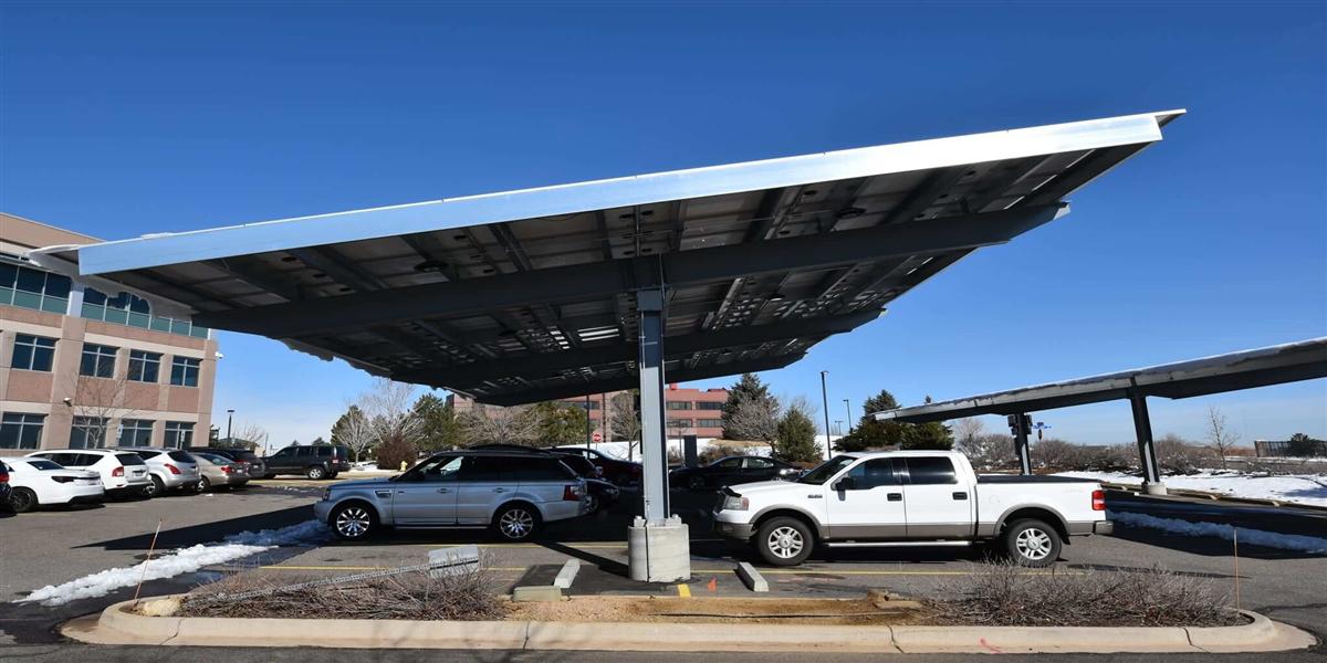
The reasons are structural rather than commercial. A 60 kW DC station draws 70–95 A per phase from a 400 V three-phase supply, which fits alongside an existing building load in most small and medium commercial services without a transformer upgrade. It serves the dominant real-world use case — a vehicle arriving at 30–50% state of charge and staying 40–90 minutes — delivering a full charge inside the visit. It is also the largest rating at which a carport-mounted 60–100 kWp array covers a meaningful share of demand.
Above 60 kW, site electrical capacity binds before capital does. Below 60 kW, DC charging loses its operative meaning. The 60 kW class occupies the productive middle.
What Makes a Microgrid “Smart” in 2026
A microgrid is not simply a site with solar panels and a battery. It is an electrical entity that can operate connected to, or independently from, the distribution grid, with a controller that balances generation, storage, and load within defined limits at all times. Five functions separate a smart microgrid from an assembly of components.
- Seamless islanding and reconnection. On a grid fault, the controller opens the point of common coupling, establishes a local voltage and frequency reference, and continues serving charging load from PV and storage. When the grid returns, it re-synchronises without dropping active sessions.
- Deterministic energy dispatch. The controller decides, second by second, where each kWh comes from: PV, battery, grid, or a combination. That decision is made against a cost function — tariff bands, demand-charge exposure, battery state of health — not a fixed schedule.
- Coordinated charging (smart power sharing). Multiple vehicles plugged into a 60 kW station share available power dynamically rather than queuing at fixed allocations. If the PV output drops or the battery reaches its discharge floor, the controller rebalances in real time.
- Tariff and market response. The site reads dynamic price signals, or a time-of-use schedule, and shifts flexible load accordingly. Increasingly this includes participating in demand-response events as a single aggregated asset.
- Predictive operation. Irradiance forecasting, vehicle arrival forecasting, and load forecasting feed the dispatch engine. Forecast quality is the single largest determinant of realised savings, because it lets the site store energy it will certainly need rather than reacting after the fact.
Two of these functions — islanding and coordinated charging — require the charging station to be designed as a grid-interactive device, not a standalone appliance. That is a procurement distinction with long-term financial consequences.
Reference Architecture for a 60kW Solar PV Microgrid
The table below describes the components, ratings, and interfaces of a typical deployment: a commercial or institutional site adding 60 kW of DC charging under a 75 kWp carport array.
| Layer | Specification for a 75 kWp / 60 kW site | Function |
|---|---|---|
| PV array | 75–120 kWp, bifacial modules, carport or rooftop mounted | Primary daytime generation |
| DC bus | 1,000–1,500 V DC, PV, battery, and charging modules on one bus | Loss-minimising coupling |
| Storage | 120–200 kWh LFP, 60–100 kW bidirectional converter | Shifting, peak shaving, island support |
| Charging output | 60 kW DC across 2 outputs (or 4 shared), wide-voltage 200–1,000 V | Vehicle charging |
| Microgrid controller | Site controller with islanding logic, load/generation forecasting, tariff engine | Dispatch, protection coordination, resilience |
| Charger management | OCPP 2.0.1 backend, ISO 15118 Plug & Charge | Sessions, billing, roaming |
| Monitoring and security | SunSpec/Modbus for assets, TLS 1.3, role-based access, signed firmware | Observability, cyber security |
| Grid interface | Point of common coupling with anti-islanding protection per local grid code | Safe interconnection |
The critical engineering decision is where the coupling occurs. In a DC-coupled design, PV and battery share the charging station’s DC bus, so solar energy reaches the vehicle through one DC/DC stage rather than through an inverter, an AC bus, and a rectifier. That single decision improves PV-to-vehicle efficiency from roughly 86% to 94% and reduces the component count — fewer parts, fewer failure modes, less maintenance.
Comparing Microgrid Topologies for a 60kW Station
| Topology | Round-trip efficiency (PV→vehicle) | Capital cost | Best fit | Main drawback |
|---|---|---|---|---|
| Standalone PV + AC chargers + no storage | 88–90% | Lowest | Pure daytime charging with trivial load | Exports midday surplus at low value; no resilience |
| PV + AC-coupled storage + AC chargers | 86–88% | Medium-high | Retrofits to existing charging sites | Two extra conversion stages; more components |
| PV + DC-coupled storage + DCDC chargers | 92–95% | Medium | New builds, most commercial sites | Requires one accountable vendor for bus control |
| Full microgrid with islanding and V2G readiness | 92–95% | Medium-high | Critical fleets, weak-grid sites, resilience mandates | Controller complexity; needs commissioning expertise |
For most new deployments, the DC-coupled column is the correct default. The AC-coupled column remains valid where chargers and storage already exist and were supplied by different vendors, since retrofit integration at the AC bus avoids rewiring the site.

2026 Deployment Drivers You Should Factor Into the Business Case
Three regulatory and market developments shape project economics this year.
Charging corridor and building mandates. European alternative-fuels regulation and analogous programmes elsewhere require charging capability at defined intervals and at new or renovated buildings — favouring compact, PV-integrable stations that can be permitted quickly.
Grid-interactive building programmes. Utilities and regulators increasingly reward sites that can reduce, shift, or curtail load on request. A 60 kW station with storage and a responsive controller is a qualifying asset, and the incentive can fund 15–40% of the storage cost in some jurisdictions.
Dynamic and capacity-based tariffs. As more markets move to time-of-use and dynamic pricing, the value of a controllable battery behind the meter rises. Sites still on flat tariffs can rarely justify storage from arbitrage alone; sites on dynamic tariffs frequently can.
Vehicle-to-everything readiness. Bidirectional charging is moving from pilot to product. Specifying a 60 kW station and a storage converter that support bidirectional power flow today avoids a future replacement cycle, even if the site activates the functionality later through a firmware update and a tariff amendment.
Sizing Rules for the 60 kW Solar PV Station
| Site profile | PV array | Storage | Daily charging energy | Self-consumption |
|---|---|---|---|---|
| Workplace, 4–6 bays, daytime arrival | 60–75 kWp | 100 kWh | 180–250 kWh | 85–92% |
| Retail or hospitality, 2 bays, 60–120 min dwell | 50–75 kWp | 100–150 kWh | 200–320 kWh | 78–88% |
| Residential community, 2–4 bays, evening arrival | 60–90 kWp | 150–250 kWh | 150–250 kWh | 75–85% |
| Small fleet depot, 6–10 vans, overnight return | 75–120 kWp | 200–300 kWh | 350–550 kWh | 70–82% |
| Clinic, campus, or critical facility | 60–100 kWp | 150–300 kWh | 120–250 kWh | 80–90% plus resilience |
The governing relationship is simple: storage energy must cover the gap between when solar is generated and when vehicles arrive. A workplace site with daytime arrivals needs only a thin buffer; a residential or depot site with evening arrivals needs two to three hours of evening load, which is why its storage is proportionally larger.
Two secondary rules prevent common failures. First, converter power should be at least 80% of charger rating, otherwise the battery cannot support a simultaneous two-vehicle session. Second, PV array sizing should be based on the site’s annual energy need divided by local specific yield, then adjusted upward for winter. In a temperate climate with 1,100 kWh/kWp annual yield, a 250 kWh daily requirement implies roughly 80–85 kWp before seasonal adjustment.
Economics: What a Smart 60kW Microgrid Returns
| Metric | Typical range | Comment |
|---|---|---|
| Installed cost, 60 kW station + 75 kWp PV + 100 kWh storage | $145,000–$210,000 | Excludes incentives; includes controller and commissioning |
| Annual energy delivered | 65,000–120,000 kWh | Two vehicles, 2–4 sessions/day each |
| Energy cost reduction vs. grid-only | 35–55% | Driven by self-consumption and arbitrage |
| Demand charge reduction | 40–60% | Storage shaves the charger’s contribution to peak |
| Simple payback without incentives | 5–7 years | |
| Simple payback with incentives | 3–4.5 years | Programmes vary widely by market |
| Availability including islanding | 99%+ | Islanding covers grid outage hours |
An important caveat: these numbers assume the site has load other than EV charging. Where charging is the only load, the microgrid still works, but revenue quality depends more heavily on the charging tariff, and the business case should be modelled accordingly.
Commissioning and Operational Best Practices
Deployments that underperform their model almost always fail at commissioning, not at specification. A structured handover includes:
- Interval-data baseline. Record 4–12 weeks of pre-installation site load at 15-minute resolution. Without a baseline, no one can prove or improve savings.
- Islanding test under load. Verify that a full-power charging session continues through a simulated grid loss and through reconnection.
- Dispatch strategy tuning. Run the controller against real tariff data for a full billing cycle and adjust the cost function before declaring the project complete.
- Protection coordination review. Confirm settings at the point of common coupling, especially where the site has on-site generation and utility protection requirements.
- Cyber-security hardening. Disable unused services, rotate credentials, enable signed firmware and TLS-only communications, and document the update process.
- Operator training and escalation path. Site staff should know how to read state of charge, force a grid-connected or islanded mode, and report a fault with useful diagnostics.
Sites that complete all six steps typically reach 90–100% of projected benefit within the first quarter. Sites that skip steps two and three commonly stall at 60–70%.
Procurement Checklist for 60kW Solar PV Charging in 2026
- Require an integrated controller that manages PV, storage, charging, and the grid interface as one system, with documented islanding logic.
- Specify OCPP 2.0.1 and ISO 15118 support so vehicles can authenticate, bill, and participate in smart charging without custom integrations.
- Confirm wide-voltage output (200–1,000 V DC) to serve the full current vehicle parc, not just 400 V-class cars.
- Ask for a modelled 12-month savings projection based on your interval data and local tariff, with the assumptions disclosed.
- Validate converter-to-charger power matching (≥80%) and check that two simultaneous sessions are supported at the rated output.
- Demand certified storage — IEC 62619, UL 9540/9540A where relevant — plus thermal-runaway test evidence and fire-suppression design details.
- Verify bidirectional readiness and ask what firmware or hardware would be required to activate V2B or V2G later.
- Check spares and service response times in your region; a 60 kW station that waits three weeks for a module replaces the entire value of the storage it controls.
Where MIDA’s Platform Fits a 2026 Microgrid Project
MIDA Power supplies the full stack a 60 kW solar microgrid requires: DC charging stations, wide-voltage charging modules for EV applications, storage integration, and PV components, engineered under one design language and one control interface. That matters because the microgrid controller’s job becomes tractable when every asset shares a protocol and a firmware lineage. MIDA’s broader EV charging and energy storage portfolio spans portable chargers, AC wallboxes, 60–240 kW DC stations, and the larger integrated architectures described in the 200kWh solar BESS EV charging station for zero-emission sites — the same reference design, scaled. And where a site’s fleet grows to include buses or heavy trucks, the platform extends to the 600kW–720kW liquid-cooled DC charging station for EV trucks and buses without abandoning the microgrid architecture built around the original 60 kW node.
FAQ
1. What exactly does a 60kW solar PV EV charging station charge?
At 60 kW DC, the station typically serves two vehicles simultaneously at 30 kW each, or shares output dynamically across four connectors. A 75 kWh passenger EV adds roughly 200–280 km of range in 60 minutes, and a light commercial van adds 120–180 km in the same window.
2. Do I need a battery to make a solar charging station work?
Not always, but self-consumption without storage rarely exceeds 35–45% unless vehicles are reliably present at midday. Storage lifts self-consumption above 80% and adds peak shaving, arbitrage, and islanding. On sites with evening arrivals, storage is effectively mandatory for a credible business case.
3. What is the difference between a solar carport and a smart microgrid?
A carport is a mounting structure with panels. A microgrid is an electrical system with a controller that can island, dispatch, coordinate charging, and respond to tariffs. The two are often combined, but the commercial value lives in the controller and storage, not the structure.
4. Can a 60kW station keep charging during a grid outage?
Yes, if it is paired with storage and a controller with islanding capability, and if the point of common coupling is designed for it. The duration depends on storage capacity and charging load: 100 kWh of storage supports roughly 70–80 minutes of continuous 60 kW output, or considerably longer at reduced power.
5. How much roof or carport area does a 75kWp array need?
Roughly 350–500 m² for fixed-tilt modules at typical spacing, or 300–400 m² for a carport canopy covering eight to ten parking bays. Bifacial modules on a canopy can add 5–15% yield from ground reflection.
6. What standards should the station comply with?
Charging interfaces and communication: OCPP 2.0.1, ISO 15118, IEC 61851 and IEC 62196 for connectors. Storage: IEC 62619, plus UL 9540/9540A in North America. Grid interconnection: local grid code requirements such as IEEE 1547 or EN 50549, with certified anti-islanding protection.
7. How long does a 60kW solar microgrid take to deploy?
From signed order to energised site, typically 16–26 weeks: 4–8 weeks of design and permitting, 8–14 weeks of equipment manufacture, and 3–5 weeks of installation, commissioning, and dispatch tuning. Sites requiring a grid capacity increase or new transformer should add 6–18 months for that element alone — which is precisely why a storage-buffered 60 kW station is often the faster path to operation.
Post time: Sep-15-2026


