
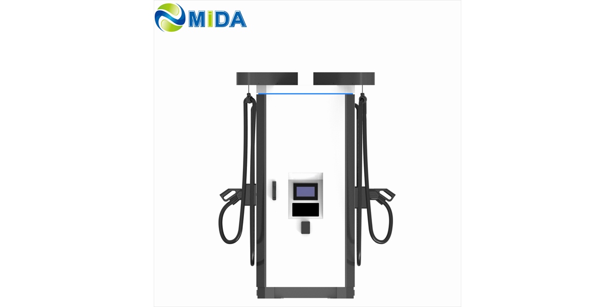
Why Distributed DC Charging Systems Are Replacing Traditional Floor-Standing EV Piles
Quick Answer
Traditional floor-standing DC piles concentrate rectifiers, control electronics, and cable management into a single pedestal at every parking stall. Distributed DC charging systems break that monolith apart: a shared power cabinet handles AC-to-DC conversion and dynamic power allocation, while slim dispensers sit at the stalls. The shift is driven by four forces — capped grid connections, rising land costs, uptime obligations, and the need for staged investment. Operators replacing floor-standing piles report higher energy utilization per installed kilowatt, fewer service points, and the ability to add stalls without renegotiating site power. Distributed architecture is not a niche configuration; it is becoming the default reference design for hubs above 300 kW.
Key Takeaways
- Floor-standing piles scale linearly; distributed systems scale sub-linearly. Ten pedestals require ten rectifier stacks, while one cabinet can serve eight to twelve dispensers from a single conversion asset.
- Grid capacity, not charger count, is the binding constraint. Pooling rectifiers behind a site-level power ceiling lets a hub serve more vehicles from the same transformer.
- Service economics favor concentration. One cabinet plus N dispensers generates one prime service location instead of N weather-exposed ones.
- Site yield improves. Removing 1.2–2.0 m² of equipment from each bay recovers parking stalls and reduces civil works.
- Migration is incremental. Existing AC infrastructure and grid connections can be retained while DC capability is added in phases.
The Problem With the Pedestal Model
For a decade, the industry’s default mental image of DC fast charging has been a tall cabinet beside a parking space, with a heavy cable draped from a hook. That image made sense when DC charging meant 50 kW and a single vehicle type.
It stopped making sense when hubs began specifying 600 kW and 720 kW. At those levels, the floor-standing pedestal becomes an exercise in forced compromise. The rectifier modules, magnetics, cold plates or heatsinks, fans, contactors, and meters must all fit inside an enclosure that also has to be pleasant enough to stand in a retail forecourt. Engineers respond by shrinking thermal margins, reducing module counts, and accepting derating. The result is a charging unit that performs well on a datasheet and poorly on a 38 °C afternoon with four vehicles charging simultaneously.
The deeper problem is economic. A pedestal is a dedicated power asset. It converts its own rectifiers, serves one vehicle, and idles the rest of the time. Across a hub with 40% average utilization, more than half the installed conversion capacity is stranded capital at any moment. Distributed architecture exists to recover that capital.
What “Distributed DC Charging” Actually Means
A distributed DC charging system separates three functions that floor-standing piles bundle together:
- Power conversion — AC-to-DC rectification, housed in a shared power cabinet.
- Power allocation — a DC bus and controller that distributes available power across active dispensers.
- User interface and delivery — the dispenser, cable, connector, and payment or authentication interface at the stall.
The physical result is a two-tier topology. The cabinet sits in a plant room, equipment yard, or landscaped enclosure. Dispensers sit at the stalls, connected by factory-terminated DC distribution. The DC link is what makes the separation practical: at 750–1000 V DC, current is low enough per kilowatt that distribution runs of 20–80 meters are achievable with manageable conductor sizes and acceptable losses.
This topology is described in more depth in the split-type architecture comparison, where cabinet and dispenser combinations are mapped to project sizes.
The Four Forces Driving Replacement
Force One: Grid Connections Are the Scarce Resource
In most markets, the cost and lead time of a new or upgraded grid connection now exceeds the cost of the charging hardware itself. Waiting eighteen months for a 1 MVA upgrade is not a hardware problem — it is a project-killing constraint.
Distributed systems address this structurally. Because rectifiers are pooled and power is dynamically allocated, the hub’s coincident demand can be held below the connection limit while stall count grows. A site with a 500 kVA connection can host eight stalls with a pooled 480 kW cabinet, even though eight independent 180 kW pedestals would nominally demand 1.44 MW.
Site-level power management turns the connection into a budget rather than a ceiling. The controller can sequence sessions, cap simultaneous output, or reserve capacity for priority vehicles.
Force Two: Land and Bay Yield
Every square meter inside a parking bay has an opportunity cost. A floor-standing pedestal occupies 1.2–2.0 m² including service clearance, needs a reinforced foundation, and frequently reduces the usable parking envelope because drivers avoid the stall adjacent to it.
A slim dispenser occupies 0.3–0.7 m² and needs only an anchor point. In a 60-stall urban garage, converting twenty bays from pedestals to dispensers can recover the equivalent of two to three additional parking spaces per row — a measurable revenue difference in cities where parking is priced by the hour.
Force Three: Uptime Obligations
Commercial charging now carries contractual availability targets. Fleets sign service-level agreements with penalties; retail hosts measure performance by revenue per stall.
A floor-standing pile has an indivisible failure domain. If its rectifier module fails, that stall is offline. If its cable management fails, that stall is offline. Mean time to repair depends on a technician arriving with the correct module and the physical ability to work safely in the bay.
A distributed system with N+1 redundancy in the cabinet degrades gracefully. Module failure reduces aggregate capacity, and the controller rebalances output. Vehicles continue charging. Repairs happen in a controlled equipment zone on a scheduled visit rather than at night in a public parking area.
Force Four: Staged Investment
Charging demand forecasts are uncertain. Building for the five-year scenario on day one ties up capital in equipment that may sit idle for years.
Distributed architecture converts an all-or-nothing build into a sequence. Install the cabinet sized for the eventual load, install dispensers according to current demand, and add dispensers as utilization crosses thresholds. The grid connection, civil works, and DC backbone are built once. Incremental cost per new stall is then a dispenser and a short DC run.
Comparison: Floor-Standing Piles vs Distributed DC Systems
| Criterion | Traditional Floor-Standing DC Piles | Distributed DC Charging Systems |
|---|---|---|
| Conversion units | One per stall | One per hub (shared) |
| Power allocation | Independent per unit | Dynamic across all dispensers |
| Utilization of installed kW | 30–60% typical | 70–90% with allocation |
| Redundancy model | Replace whole unit | N+1 modules in cabinet |
| Equipment footprint per stall | 1.2–2.0 m² | 0.3–0.7 m² |
| Civil works per stall | Foundation + AC feed each | Anchor point + DC run |
| Service locations | One per stall | One per cabinet |
| Expansion cost per stall | Full charger cost | Dispenser + DC run |
| Suitability above 400 kW | Constrained by thermal and space limits | Native design target |
Technical Enablers That Made the Shift Possible
Three engineering advances turned distributed architecture from theory into a commercially dominant design.
Wide-bandgap power modules. Silicon carbide and advanced IGBT modules deliver higher conversion efficiency in smaller volume, allowing 20–40 kW per module and raising cabinet power density to 40–60 kW per rack unit footprint. Higher-density modules mean fewer racks, smaller cabinets, and better serviceability. MIDA’s charging modules for EV infrastructure illustrate how module-level efficiency and thermal design determine cabinet capability.
Liquid cooling at the cabinet. Liquid-cooled cabinets dissipate heat through a closed loop rather than pushing large air volumes through filters in a public space. This supports full-rated output at high ambient temperatures, reduces acoustic signature, and eliminates the filter-maintenance burden that plagues air-cooled pedestals in dusty environments.
High-voltage DC distribution. Operating the internal DC bus at 750–1000 V reduces current per kilowatt, which in turn reduces conductor cross-section and losses on long cabinet-to-dispenser runs. Combined with digital isolation monitoring, this makes remote cabinet placement safe and practical.
Deployment Patterns That Work
Retail and mixed-use forecourts. Cabinet in a back-of-house plant area; four to eight dispensers along the parking row. Signage and payment at the dispenser; noise and heat away from customers.
Urban garages. Cabinet in a basement electrical room with ventilation; slim dispensers mounted on columns or walls. This pattern also resolves ceiling-height and structural loading problems that block pedestal installation.
Fleet depots. High stall count, low cost per stall, overnight sessions. Pooled power with scheduled allocation avoids expensive demand spikes and matches depot electrical supply.
Highway corridors and heavy vehicles. Long dwell distances and high power per vehicle favor a cabinet paired with heavy-duty dispensers. MIDA’s 600 kW–720 kW liquid-cooled DC charging station is built around this pattern for trucks and buses, where cable management and dispenser placement flexibility are decisive.
Solar and storage coupled hubs. A shared DC bus in the power cabinet allows battery and grid inputs to feed the same conversion stage, which is the architecture behind many zero-emission site designs, including this 200 kWh solar BESS EV charging station case.
What to Verify in a Distributed System Specification
- Module-level redundancy. Confirm N+1 minimum, and ask for the derated output curve when one module is offline.
- Dynamic allocation logic. Request documentation of how power is shared when stall demand exceeds cabinet capacity.
- DC run limits. Get maximum distances by output current, and confirm voltage-drop calculations.
- Cooling type and ambient rating. Insist on the full-power ambient temperature, not the operating range.
- Protection and isolation. Verify insulation monitoring, DC residual current detection, and surge protection on the AC input.
- Communication protocols. OCPP 1.6J or 2.0.1 for back-end integration, plus local energy management interfaces.
- Serviceability. Confirm module swap time, spares availability, and whether replacement requires specialized tooling.
Common Objections, Answered
“Doesn’t distributing power create new failure points?” It creates a single critical asset — the cabinet — which is precisely why redundancy belongs there. Designing N+1 at one location is cheaper and more effective than designing partial redundancy into ten pedestals.
“What if the DC cable is damaged?” Factory-terminated, armored DC runs with isolation monitoring detect faults quickly and localize them to a segment. This is a bounded, maintainable risk, unlike a pedestal where a rectifier fault strands the whole unit.
“Can I mix AC and DC on the same site?” Yes. AC wallboxes remain appropriate for long-dwell parking, and a distributed DC backbone can be layered onto the same site without conflicting.
“Is distributed architecture only for very large hubs?” No. A 240 kW cabinet with three dispensers is a legitimate distributed configuration for a mid-size site, and it is expandable.
Bottom Line
Floor-standing piles were the right answer when DC charging was a novelty and grids were plentiful. Neither condition holds today. Capped grid capacity, expensive land, contractual uptime, and uncertain demand forecasts all push toward architectures that pool conversion, distribute delivery, and expand in increments. Distributed DC charging is not a trend to evaluate — it is the reference design that traditional pedestal deployment is being measured against.
FAQ
What is a distributed DC charging system?
It is a charging architecture in which a shared power cabinet performs AC-to-DC conversion and dynamic power allocation, while power is delivered to vehicles through separate dispensers located at the parking stalls. The cabinet and dispensers are connected by a DC distribution run.
How many dispensers can one power cabinet support?
Most commercial power cabinets support two to eight dispensers directly, with larger configurations reaching twelve or more through additional DC outputs. The limit is set by cabinet rectifier capacity, output current per dispenser, and DC run distance.
Does distributed charging reduce peak demand charges?
Yes, when site-level power management is enabled. Because the cabinet controls aggregate output, the hub can cap coincident demand below a configured ceiling. Pedestal-based hubs have no equivalent lever without adding external load management.
Is power shared fairly between dispensers?
Modern controllers allocate available capacity using configurable rules — first-come-first-served, equal share, priority by vehicle class, or time-based sequencing. The allocation logic should be documented and adjustable through the back-end platform.
Can distributed DC systems run alongside existing AC chargers?
Yes. AC charging remains appropriate for long-dwell applications. A distributed DC backbone is installed independently and both can be managed through a common back-end.
What is the typical payback difference versus floor-standing pedestals?
It depends on utilization and stall count, but at hub scale the difference typically appears in two places: lower capital cost per stall above six stalls, and lower service labor cost per stall over the operating period. Utilities and demand charges usually add a third, site-dependent benefit.
Do distributed systems work in cold climates?
Yes, provided the cabinet includes heating for the electronics and the specified operating range covers the site minimum. Dispensers have fewer heat-generating components and generally tolerate cold better than integrated pedestals.
Conclusion
The replacement of floor-standing piles is being driven less by preference than by arithmetic. Pooled conversion raises utilization of installed power, flexible placement raises site yield, concentrated service lowers maintenance cost, and incremental expansion reduces investment risk. For any project above roughly 300 kW — and for most projects that expect to grow at all — distributed DC charging is the design that survives contact with real grid limits and real balance sheets.
Post time: Sep-16-2026


