
Future-Proofing Your Site: Scaling from 120kW to 960kW with Split Infrastructure
Meta description: A staged growth roadmap for charging sites: how split architecture lets operators scale from 120kW to 960kW by adding modules, cabinets, and dispensers — without rebuilding the yard, retrenching cables, or re-permitting the site.
Quick Answer
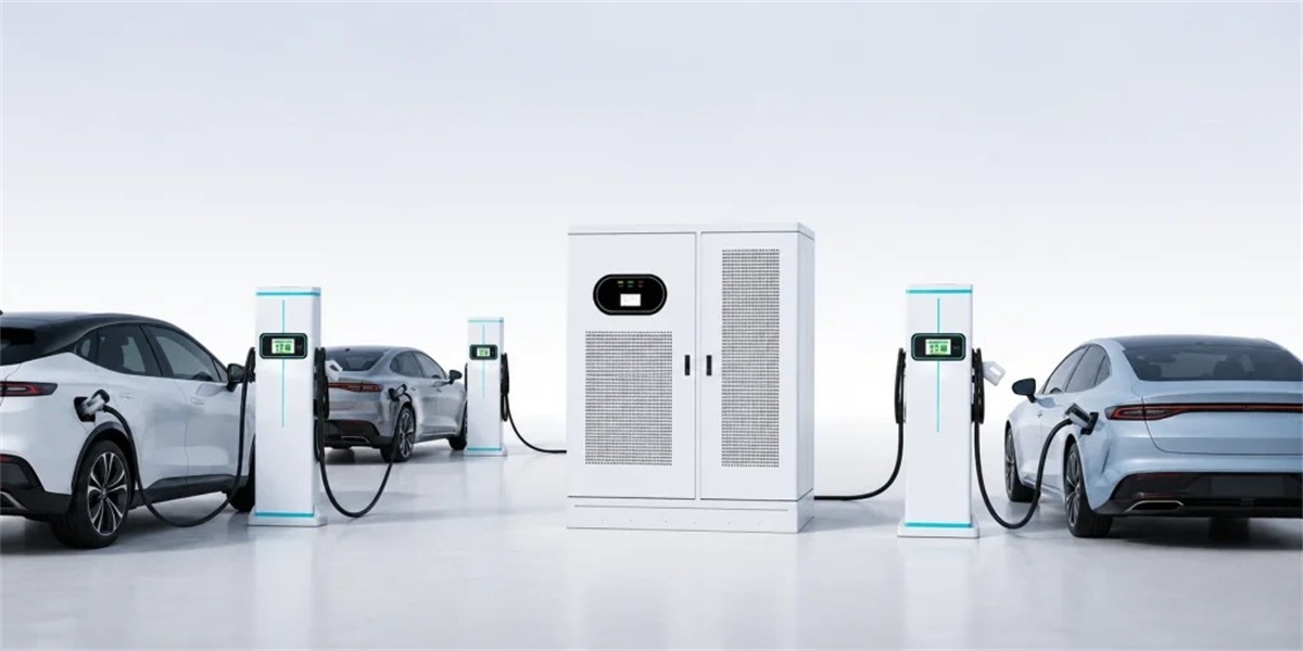
Scaling from 120kW to 960kW with split infrastructure means adding capacity in modular steps instead of replacing stations. A split site separates the power cabinets (AC/DC modules, cooling, switchgear) from slim dispensers at the parking bays, all connected by a shared DC bus. An operator can start with a single 120kW cabinet serving two lanes, add 40kW modules to reach 240kW, add cabinets to reach 480kW, and continue to 960kW or beyond by expanding the module pool — while the dispensers, trenching, transformers, and permits already in the ground remain valid. The critical discipline is to size the permanent parts of the site (transformer, switchgear, conduit, coolant routing, power-room floor area) for the 960kW end state on day one, and buy only the capacity needed today.
Key Takeaways
- Split architecture turns capacity into a variable, not a fixed asset. Modules and cabinets are the growth unit; civil works and permits are built once for the final target.
- Modular growth beats single-leap investment. Staged energization matches capital to actual traffic, deferring the largest costs until revenue justifies them.
- Day-one civil sizing is the one irreversible decision. Undersized transformer capacity, conduit, and power-room space are the most expensive mistakes in charging infrastructure.
- Each step has its own economics. 120kW serves early light-duty demand, 240–480kW covers mixed fleets, and 960kW is where heavy-duty and megawatt-adjacent duty becomes viable.
- Software must scale as fast as the copper. Site-limit control, dynamic power sharing, and OCPP 2.0.1 integration keep a growing site inside its grid contract.
The Stranded-Asset Problem Split Architecture Solves
Most charging sites are built twice: once optimistically, once correctly. The pattern is familiar. An operator installs two integrated 60kW or 120kW chargers to open a location. Within eighteen months, utilization doubles, vehicles with larger batteries arrive, and session durations stretch past what customers will tolerate. The upgrade path for integrated units is replacement — new stations, new pads, new connections, occasionally a new transformer and a fresh permitting cycle. The original hardware is written down before its service life ends.
Split architecture removes that forced write-off by separating capacity from infrastructure:
- Capacity lives in modules (40kW or 60kW hot-swappable units) and cabinets, both of which are added incrementally.
- Infrastructure lives in trenches, busbars, transformer capacity, switchgear, and power-room space, all of which are sized once for the final target.
- Driver-facing hardware lives in dispensers, which are added as lanes are commissioned and replaced independently when connector standards change.
The result is a site whose cost grows in steps that match revenue — while its permanent assets never become obsolete.
The Growth Ladder: 120kW → 240kW → 480kW → 960kW
Each step changes what the site can do, not just how much power it draws. A representative progression:
| Stage | Configuration | Typical Lanes | Duty Served | Session Profile |
|---|---|---|---|---|
| Stage 1 | 1 × 120kW cabinet (3 × 40kW modules), 2 dispensers | 2 | Light commercial, early passenger EV demand | 60–120kW per lane, 30–45 min sessions |
| Stage 2 | 240kW (6 × 40kW modules), 4 dispensers, sharing enabled | 4 | Mixed passenger and light commercial | 60–150kW per lane, 25–40 min sessions |
| Stage 3 | 480kW across two cabinets, 4–6 dispensers | 4–6 | Mixed fleet including 800V passenger and vans | 120–300kW per lane, 20–35 min sessions |
| Stage 4 | 960kW across four cabinets, 6–8 dispensers | 6–8 | Heavy-duty, high-throughput hubs, megawatt-adjacent | 240–480kW+ per lane, 20–40 min sessions |
Two design rules make the ladder work. First, every stage must share the same DC bus and control platform, so added cabinets join the existing pool rather than operating as isolated islands. Second, per-lane cabling and dispenser bases should be specified at the final-stage rating from the start — a dispenser base and conduit sized for 480kW costs marginally more than one sized for 120kW, but re-excavating a live site later costs multiples of that difference.
Sizing the Permanent Elements on Day One
The most valuable planning work happens before any concrete is poured. Four elements should be sized for the 960kW end state even if the site launches at 120kW:
- Transformer capacity. A 960kW DC load generally implies a dedicated 1,000–1,250kVA transformer, or reallocated capacity of equivalent size. Reserving that capacity and physical space at the start avoids a utility capacity application later — often a 12–24 month critical path.
- Switchgear and main distribution. Specify breakers, busbars, and metering for final-stage currents. Upsizing switchgear at installation is inexpensive; replacing an energized main board is not.
- Conduit and trenching. Route ducts, cable trays, and coolant pathways for the maximum dispenser count. Trenching is 80–90% labour; the marginal cost of a larger duct bank is trivial.
- Power-room floor area and thermal design. Modular cabinets need floor space, service clearance, and ventilation or cooling capacity for the final module count. Leaving room for two additional cabinets is free at design stage and impossible afterwards.
Add a fifth, software-side element: site-limit control and dynamic power sharing configured for the final capacity from day one. The controller should know the site’s grid ceiling before the site reaches it, so growth never causes a demand-charge event.
Phased Energization and Grid Strategy
Staged growth is also a grid-financing strategy. Utilities charge for capacity, and interconnection queues in many markets run to multiple years for large new loads. Split architecture allows operators to:
- Commission in increments. Energize 120kW or 240kW first, then apply for additional capacity as utilization data justifies it.
- Buffer peaks with storage. A battery energy storage system charged overnight and discharged during peaks can serve additional lanes without raising the contracted capacity, often cutting demand charges 30–50%.
- Keep options open. Because cabinets are modular, an operator who secures transformer capacity for 960kW can choose when to fill it rather than committing capital early.
For sites in constrained grid areas, the combination of modular cabinets and on-site storage is the only realistic route to high-power service within a competitive timeframe.
Economics of Scaling: Capital in Steps, Revenue in Steps
Staged investment is not a compromise; it is a better financial structure. The table below illustrates how capital exposure and capability track each other.
| Stage | Incremental Hardware Addition | Site Capability | Capital Exposed Early | Risk Profile |
|---|---|---|---|---|
| 1 → 2 | 3 additional 40kW modules, 2 dispensers | 240kW, 4 lanes | Low | Utilizes installed infrastructure fully |
| 2 → 3 | 1 additional cabinet, 1–2 dispensers | 480kW, 4–6 lanes | Moderate | Triggers step-change in throughput |
| 3 → 4 | 2 additional cabinets, 2 dispensers, possible storage | 960kW, 6–8 lanes | Higher | Enables heavy-duty and fleet contracts |
Compare this with the integrated alternative, where each step requires new station hardware, new pads, and frequently a fresh electrical connection. Over a five-year horizon, operators report materially lower lifetime cost for the modular path — driven by avoided civil works, avoided permits, and maintenance concentrated in one accessible power room rather than distributed across many stations.
There is also a demand-side benefit: because hardware is added against demonstrated utilization, the site’s capital efficiency stays high and under-utilized assets never sit on the balance sheet.
Software, Protocols, and Compatibility Across Stages
A site that grows physically must also grow logically. Three requirements keep expansion frictionless:
- One control platform. All cabinets and dispensers should report to a single charge management system over OCPP 2.0.1, so billing, roaming, and reporting are consistent through every stage.
- Dynamic power sharing across cabinets. Growth should add to a shared power pool, allowing, for example, 480kW to a truck on one lane while vans charge at 60–120kW on others from the same cabinets.
- Standards continuity. ISO 15118 Plug & Charge, RFID, and payment terminal support should be specified from Stage 1 so driver experience does not change as capacity grows.
Plan the connector mix, too. CCS2 remains the European baseline, CCS1 and NACS dominate North America, and GB/T is essential for Chinese fleets. Specifying dual-cable dispensers at later stages — and dispenser bases designed for them from the start — avoids the scenario where a physically capable site cannot serve the vehicles arriving in its bays.
A Practical Expansion Checklist
- Model the traffic, not the ambition. Size Stage 1 against realistic first-year session volume.
- Design the final layout on paper first. Dispenser positions, cable routes, cabinet room, and coolant loops should be drawn at 960kW scale before Stage 1 is installed.
- Reserve grid capacity and power-room footprint. Document the final requirement in utility applications even if the initial connection is smaller.
- Standardize on one module platform and one control platform. Mixed generations complicate sharing and service.
- Specify hot-swappable, individually monitored modules. Expansion and repair use the same procedure.
- Buy the redundancy level you intend to keep. Adding modules later to reach N+1 is possible; designing for it from the start is cheaper.
- Track delivered kWh per lane, not nameplate kW. That metric tells you precisely when the next stage is justified.
MIDA’s Modular Split Platform for Staged Growth
MIDA Power designs its DC platform so that growth is a procurement decision rather than a construction project. Cabinets built around hot-swappable 40kW/60kW liquid-cooling power modules scale from 240kW to 960kW and beyond on the same bus, with module-level telemetry that makes per-lane utilization visible from the first day of operation.
Where a site needs attended operation, payment, access control, and metering at the dispenser, the 360kW liquid-cooled station with RFID, OCPP and POS shows how the same architecture serves driver-facing requirements without adding a separate hardware silo. Motorway-grade durability is documented in the 480kW liquid-cooled ultra-fast station deployed on high-traffic corridors, the same duty profile that Stage 3 and Stage 4 sites will encounter.
The portfolio is certified to TUV/CE/UL for global deployment and supports OCPP 2.0.1 with ISO 15118 Plug & Charge, so billing and roaming survive each expansion stage. Operators scoping a multi-year build-out can review the full commercial DC fast charging range to map cabinet power, dispenser counts, and connector options onto their growth plan.
FAQ
1. Can I really start at 120kW and grow to 960kW with the same equipment?
Yes, provided the site is designed for the end state. The cabinets and DC bus support incremental module and cabinet additions; dispensers, trenching, and switchgear are built once. The constraint is day-one civil and grid planning, not the equipment platform.
2. What has to be oversized at the start, and what can wait?
Transformer capacity and space, switchgear ratings, conduit and trenching, coolant routing, and power-room floor area should be sized for 960kW from the beginning. Power modules and cabinets themselves can be purchased later, in step with demand.
3. How much extra does it cost to plan for 960kW while installing 120kW?
Typically a modest premium on civil works — larger duct banks, reserved floor area, and switchgear ratings — often in the range of 10–20% of the Stage 1 civil scope. That premium is usually a fraction of the cost of a later re-trenching or utility capacity upgrade.
4. Do additional cabinets share power with the existing ones?
They should. A properly designed split site pools all cabinets into one DC bus with a common controller, so total site power is allocated dynamically across every dispenser instead of being siloed per cabinet.
5. How does staged expansion affect grid connection and demand charges?
Each stage increases contracted capacity only when justified by utilization. Pairing later stages with battery storage lets the site serve more lanes while keeping peak draw — and demand charges — under control.
6. When should storage be added to the growth plan?
Storage is most valuable at the transition to Stage 3 and Stage 4, when simultaneous high-power sessions become common. It buffers peaks, reduces required grid capacity, and can recharge during low-tariff hours.
7. What metrics tell me it is time to expand?
Lane-level delivered kWh per day, average queue times, session duration versus customer expectation, and utilization above roughly 15–20% per stall on a sustained basis. When delivered energy stops tracking demand, the next module or cabinet stage is justified.
Conclusion
Future-proofing a charging site is less about predicting the future than about not blocking it. Split architecture makes power conversion and cooling modular while leaving customer-facing and civil elements replaceable or permanent in the right proportions. Build the transformer, duct banks, and power room for 960kW; buy modules, cabinets, and dispensers for the traffic you actually have; and let the software manage whatever capacity exists at any moment. Operators who follow that sequence reach 960kW with a fraction of the write-offs, downtime, and permitting exposure that integrated single-leap projects incur — and they can start earning at 120kW on day one.
Post time: Sep-17-2026


