
The Role of Liquid-Cooled Split DC Chargers in the Megawatt Charging Revolution
Meta description: Why megawatt-class charging is impossible with air cooling, how liquid-cooled split DC chargers work at 1 MW and above, and what fleet operators must specify for MCS-ready sites in 2026.
Quick Answer
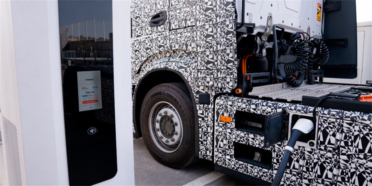
Megawatt charging is thermally impossible with air-cooled hardware. Delivering 1,000–1,250V DC at 1,000–3,000A means resistive and switching losses that must be removed continuously; liquid cooling is what allows a connector to carry three to five times the current of an air-cooled equivalent without overheating or becoming unmanageable for a driver to lift. In a split architecture, that cooling is centralized: power cabinets sit in a dedicated electrical room with their own coolant circulation units, while slim dispensers hold the liquid-cooled cable and connector. The result is a charger that sustains 1.0–1.2MW today — and up to 3.75MW in theory — while keeping heat, noise, and service access away from the truck bay. For fleets planning 2026–2030 electrification, liquid-cooled split design is not an option; it is the reference architecture for megawatt corridors.
Key Takeaways
- Current, not voltage, is the bottleneck. MCS-class connectors carry up to 3,000A; without liquid cooling the cable would be too heavy for one person to handle and would overheat within minutes.
- Liquid cooling raises sustained power, not just peak power. Cooled connectors and modules hold full output at 40–50°C ambient, while air-cooled equipment derates as temperatures rise.
- Split architecture is what makes megawatt deployment practical. Conversion and cooling stay in a central room, so dispensers at each truck bay remain compact, quiet, and inexpensive.
- Thermal design determines availability. A megawatt site lives or dies by coolant flow, filtration, and CDU redundancy — specify these as carefully as the power modules.
- The site is the long pole. Transformer capacity, medium-voltage connection, and coolant-plant civil works dominate project timelines, not the charger itself.
Why Air Cooling Reaches Its Limit at 375kW
Air cooling is adequate to roughly 300–375kW per connector, and then physics intervenes. Conductor heating scales with the square of current. Doubling current from 500A to 1,000A quadruples resistive losses in the same conductor; the cable cross-section needed to compensate grows until it becomes impractical. At 1,000A, an air-cooled cable would need such heavy copper that a driver could not reasonably handle it — a safety and ergonomics failure long before a technical one.
Engineering responses emerged in two forms. The first was increasing voltage: moving from 400V to 800V and now 1,000–1,250V platforms halves current for the same power, which is why 1,000V-capable split systems matter even before megawatt standards arrive. The second was liquid cooling, which removes heat at the source inside the cable and connector, allowing compact geometry at extreme current.
The two developments converge in the Megawatt Charging System (MCS), which targets 1,250V DC and up to 3,000A for a theoretical 3.75MW per connection. Every deployed MCS-class system uses liquid-cooled connectors, cables, power modules, and coolant circulation; there is no air-cooled path to megawatt charging.
| Parameter | Air-Cooled DC (150–350kW) | Liquid-Cooled Split DC (480kW–1.2MW) |
|---|---|---|
| Typical connector current | 200–500A | 500–3,000A |
| Cable mass per metre | 3–5 kg (heavy, stiff) | 1.5–2.5 kg (flexible) |
| Cable diameter | 25–40mm | 20–30mm with cooling jacket |
| Sustained power at 45°C ambient | Derates 15–30% | Full rated output |
| Module efficiency at full load | 94–96% | 96–97%+ |
| Cooling location | Fans inside each station | Central coolant circulation unit |
| Driver handling | Two hands, low flexibility | One hand, ergonomic |
| Noise at the bay | 60–70 dB(A) | Below 45 dB(A) |
The table explains a design decision that is often mistaken for a marketing one: liquid cooling is what converts a high-power charger from a device that peaks well to a device that performs all day in a hot parking lot.
Inside a Liquid-Cooled Split DC System
A liquid-cooled split charger has four thermal and electrical stages, each with a distinct cooling requirement.
- Power modules. Each 40kW or 60kW rectifier module sits on a cold plate; coolant removes heat directly from the semiconductor and magnetics, keeping junction temperatures low and efficiency high. Module-level liquid cooling also extends service life, since thermal cycling is the main wear mechanism in power electronics.
- Power cabinet busbar and switchgear. Aggregate currents inside a 960kW cabinet reach hundreds of amps on DC busbars. Cooled, busbars run at lower temperature and therefore lower resistance, cutting losses that would otherwise appear as heat inside a sealed enclosure.
- Coolant circulation unit (CDU). The CDU pumps coolant, rejects heat through a radiator or chiller, filters particulates, and monitors flow, pressure, and conductivity. In MCS-ready sites, the CDU is specified with N+1 pump redundancy so a single pump failure never stops a charging session.
- Cable and connector. The final and most demanding loop. Coolant circulates through the cable and connector body; the contact interface is kept within safe limits at 1,000A+ while remaining ergonomic. MCS connectors use a single connector body at hip height with automated-mating-ready geometry.
Two cooling media dominate. Water–glycol mixtures (typically 50/50) offer high heat capacity, low cost, and proven freeze protection. Dielectric coolants are used where direct contact cooling of electronics is required. Both have to be specified with maintenance intervals — filter replacement, coolant sampling, and conductivity checks — that map to site operations calendars.
Thermal Engineering Decisions That Decide Site Performance
Megawatt sites fail on thermal and electrical planning far more often than on charger capability. Four decisions matter most:
- Coolant loop length. Every extra metre of hose between cabinet and dispenser adds pressure drop and heat gain. Designing dispenser positions on a compact DC bus loop — typically under 50 metres from the cabinet — keeps pump energy low and flow stable.
- Ambient design temperature. Sizing the CDU for the site’s true summer peak, not a national average, determines whether the station delivers full power in July. In hot climates this often means a chiller-equipped CDU rather than a dry radiator.
- Dust, salt, and humidity ingress. Coolant filters and IP-rated enclosures protect radiators and connectors. Coastal and quarry sites require additional filtration and more frequent service intervals.
- Acoustic compliance. Because the cooling plant sits in a power room rather than at the bay, night-time noise limits of 55–60 dB(A) at truck stops are achievable without expensive acoustic treatment at each dispenser.
The compound effect is a higher-availability site. Centralized cooling translates to a single, accessible service point with standardized parts — the same logic that makes module-level hot swap possible in the electrical domain.
Why Split Architecture Is the Megawatt Deployment Model
Placing megawatt-scale conversion equipment at every charging bay is economically and physically impractical. A 1.2MW integrated unit would be larger than a small van, would radiate significant heat and noise into the driver environment, and would require its own high-voltage connection at each bay.
Split architecture separates the two functions:
- Central power room: power cabinets, coolant circulation units, switchgear, metering, and protection — sized once, expandable in modular steps.
- Dispensers at the bay: cable management, connector, user interface, and metering only — compact, quiet, and consistent with the site’s layout.
This model also makes staged energization viable. An operator can commission 480kW of capacity, run revenue service, and add cabinets as traffic grows — reaching 960kW, 1,440kW, and beyond without rebuilding the yard, retrenching cables, or re-permitting the site. That incremental path matches the reality of electric freight adoption, where utilization ramps over years rather than days.
What Megawatt Charging Demands of the Site
Megawatt charging is a grid-connection problem before it is a charger problem. A single megawatt-class stall draws power comparable to a small industrial facility, and multi-bay hubs frequently exceed the capacity of the existing low-voltage feed. Practical responses include:
- Medium-voltage connection. High-power hubs connect to 10–35kV utility lines through dedicated transformers rather than low-voltage distribution.
- On-site buffering. A 1–2MWh storage system charges at moderate power between sessions and discharges during peaks, reducing the required connection and avoiding multi-year interconnection queues.
- Staged capacity. Modular cabinets convert one impossible connection into manageable increments commissioned against actual demand.
Civil works should be sized for the final target on day one. Oversizing the trench, busbar, coolant routing, and transformer room is inexpensive compared with re-opening a live site later — and re-permitting is the single most common cause of megawatt project delays.
Total Cost of Ownership: Liquid-Cooled Split Versus Air-Cooled Fleet
At scale, the liquid-cooled split model wins on lifetime cost, not purchase price. Purchase cost per kW is higher than air-cooled equipment, but four cost lines move decisively in its favour:
| Cost Line | Air-Cooled Integrated Fleet | Liquid-Cooled Split System |
|---|---|---|
| Civil works | Station pad and service access at every bay | One power room, slim dispenser bases |
| Maintenance labour | Multiple distributed service points | Single service location, hot-swap modules |
| Energy losses | Higher at partial load and high ambient | 96–97% efficiency held at full load |
| Expansion | Replace station, add new connection | Add cabinets and dispensers to existing bus |
| Cable/connector life | Frequent replacement at high cycles | Cooled connectors last 10,000+ mating cycles |
| Site capacity ceiling | Limited by per-station hardware | Scales to megawatt-class by module addition |
For operators, the decisive question is not whether liquid cooling costs more upfront, but whether they can deliver the session times their customers require. Above roughly 400kW per lane, no alternative exists.
Building a Megawatt-Ready Portfolio with MIDA
A megawatt site is a system of modules, cables, connectors, cooling, and software — so single-vendor scope reduces integration risk. MIDA Power manufactures the full chain, including the 40kW/60kW liquid-cooling power modules that populate split cabinets, liquid-cooled 360kW charging stations with RFID, OCPP and POS for attended sites, and split systems scaling to 1,440kW and beyond.
The platform’s field record includes the 480kW liquid-cooled ultra-fast station used on motorway corridors, where sustained duty cycles and varying ambient conditions test cooling design continuously. Products are certified to TUV/CE/UL for global markets and support OCPP 2.0.1 with ISO 15118 Plug & Charge, so megawatt and sub-megawatt lanes can share one management platform. Operators scoping a corridor or depot build can review the full commercial DC fast charging range to match cabinet power, cooling configuration, and dispenser layout to their traffic model.
FAQ
1. Why is liquid cooling mandatory for megawatt charging?
Because current, not voltage, generates the heat. At 1,000–3,000A, an air-cooled cable would need impractical copper mass and would still overheat in minutes. Liquid cooling removes heat inside the cable and connector, keeping them within safe limits and light enough for one person to handle.
2. At what power level does liquid cooling become necessary?
Practically, above roughly 375–400kW per connector. Below that, air-cooled designs with adequate cable cross-section remain viable. Above it, cooled cables and cooled power modules become the standard engineering choice.
3. What is an MCS connector rated for?
The Megawatt Charging System standard targets 1,250V DC and up to 3,000A, yielding a theoretical 3.75MW per connection. First-wave deployed hardware operates at 1,000–1,250V and 1,000–1,250A, delivering 1.0–1.2MW.
4. How often does a liquid-cooled charger need maintenance?
Typical schedules involve annual coolant sampling and filter replacement, with flow and pressure monitored continuously by the CDU. High-dust or coastal sites shorten intervals. Because cooling is centralized in a power room, the work is done in one accessible location rather than at each bay.
5. Can an existing air-cooled site be upgraded to a liquid-cooled split system?
Often yes, if the grid connection and civil works are re-assessed. In many cases the transformer and switchgear are retained, the power room is re-equipped, and dispensers are replaced. Sites with undersized connections benefit from pairing the upgrade with battery storage to cap peak draw.
6. Does liquid cooling reduce charging efficiency or increase losses?
No. Cooled power modules typically achieve higher efficiency (96–97%) because they run cooler, and cooled busbars have lower resistance. Pump and fan energy is a small fraction of the energy saved by avoiding thermal derating and conductor losses.
7. How do I plan capacity for a future megawatt upgrade today?
Size transformer capacity, trenching, busbar routing, coolant pathways, and power-room floor area for the final megawatt target, then install cabinets in modular increments as traffic grows. Design for the end state; buy for the current one.
Conclusion
The megawatt charging revolution is not a connector story — it is a thermal and architectural one. Liquid cooling is what makes extreme current physically deliverable, and split architecture is what makes it deployable at real sites without oversized hardware at every bay. Operators who specify liquid-cooled modules, redundant coolant circulation, wide voltage output, and megawatt-sized civil works today will add capacity by buying cabinets, not by rebuilding yards. That is the practical meaning of megawatt readiness in 2026.
Post time: Sep-17-2026


