
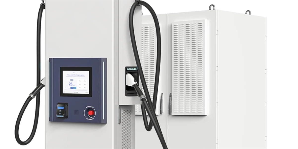
Why N+1 Redundancy in Split DC Cabinets Guarantees 99.9% Charging Reliability
Meta description: How N+1 power-module redundancy, hot-swap maintenance, and component-level fault isolation deliver 99.9% charging availability in split DC cabinets — and how operators should specify and contract for it in 2026.
Quick Answer
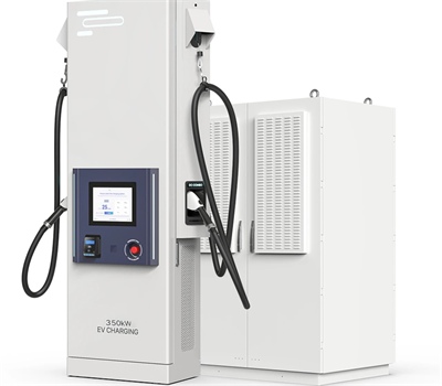
99.9% charging reliability means no more than 8.76 hours of unplanned downtime per charger per year. In split DC cabinets, that target is achieved by provisioning one more power module (or cooling pump, or controller path) than the system needs to deliver full output: an N+1 design. A 240kW cabinet built from seven 40kW modules can run on six, so a single module failure removes headroom rather than service. Combined with hot-swap replacement — typically under 15 minutes without powering down the cabinet — a fault that would otherwise cause a multi-hour truck-roll becomes a scheduled maintenance item. At the system level, module redundancy, dual-cable dispensers, dispenser failover, and redundant coolant circulation extend the same logic across the whole site.
Key Takeaways
- 99.9% is a specific number, not a slogan. It allows 8.76 hours of unplanned downtime per charger per year; 99% allows 87.6 hours, which no commercial operator can accept on a revenue asset.
- Redundancy must sit at the smallest replaceable unit. N+1 at module level protects against the most common failure — a single power module — without closing a lane.
- MTTR is as important as MTBF. A 4-hour site visit and a 15-minute hot swap produce very different availability from the same failure rate.
- Availability is a system property. Cabinet redundancy cannot compensate for single-path cooling, a single dispenser cable on a critical lane, or an unmonitored controller.
- Contracts should carry the guarantee. Availability targets belong in an SLA with measurement methods, spare-parts commitments, and response times written in.
Defining Availability in Charging Infrastructure
Availability is the probability that a charger is able to deliver its intended service when a vehicle plugs in, and it is computed from two parameters:
Availability = MTBF ÷ (MTBF + MTTR)
where MTBF is mean time between failures and MTTR is mean time to repair. The formula exposes the two legitimate engineering routes to high availability: reduce failure frequency, or reduce repair time. Redundancy does both — it prevents single failures from becoming outages, and hot-swap design collapses repair time.
| Availability Target | Unplanned Downtime per Year | What It Means Operationally |
|---|---|---|
| 95% | 18.25 days | Revenue asset, unusable as critical infrastructure |
| 99% | 87.6 hours | Roughly one full week of lost sessions per charger |
| 99.9% | 8.76 hours | Achievable with N+1 and hot-swap service discipline |
| 99.99% | 52.6 minutes | Requires cabinet-level redundancy plus storage buffering |
| 99.999% | 5.26 minutes | Data-centre economics; rarely justified at a charging bay |
The commercial case for 99.9% is straightforward. A charger delivering 1,200kWh per day at a €0.55/kWh retail rate generates roughly €240,000 of annual gross revenue. The difference between 99% and 99.9% availability is about 79 hours — on the order of €26,000 of lost revenue per charger per year, before counting damage to customer loyalty and the risk of drivers defecting to a competing hub.
What N+1 Actually Looks Like Inside a Split Cabinet
A split power cabinet is a pool of modules, and redundancy is expressed as a ratio between installed and required module count.
- 240kW cabinet, 6 modules required. N+1 means installing a seventh 40kW module. Full 240kW output continues after any single module failure. The spare module can also be rotated into service during maintenance.
- 480kW cabinet, 12 modules required. N+1 means thirteen modules. Operators who expect summer peak demand or heavy truck duty often specify N+2, accepting a modest cost increase for protection against a second coincident failure.
- Module-level fault isolation. Each module has its own rectifier stage and protection. A shorted or faulty module is electrically isolated so it cannot drag down the DC bus or interfere with active sessions.
Critically, module failure in an N+1 cabinet is invisible to the driver. No session derates, no lane closes, and the fault appears only as a diagnostic event in the monitoring platform. That is the definition of redundancy that works.
| Configuration | Installed Modules (per 240kW cabinet) | Behavior After 1 Failure | Behavior After 2 Failures | Relative Cost |
|---|---|---|---|---|
| N (no redundancy) | 6 × 40kW | Output drops to 200kW | Output drops to 160kW | Baseline |
| N+1 | 7 × 40kW | Full 240kW maintained | Output drops to 200kW | +12–17% module cost |
| N+2 | 8 × 40kW | Full 240kW maintained | Full 240kW maintained | +25–30% module cost |
Note what is not in the table: an outage. None of these configurations requires closing a lane for a module fault, provided the failed module is replaced within the redundancy window — days, not hours.
Hot-Swap: Collapsing MTTR
Mean time to repair is where most availability is lost, and hot-swap design is where it is recovered. Traditional service means diagnosing a fault, dispatching a technician, isolating the cabinet, waiting for the site to clear, replacing hardware, and re-energizing — a 4–8 hour sequence in practice, longer if the failure coincides with peak hours when a lane cannot be taken out of service.
Hot-swap modules change the sequence:
- Detection. Module-level telemetry reports the fault in real time to the maintenance platform, often before the module fully fails.
- Isolation. The module is electrically disconnected from the DC bus while the cabinet remains live.
- Replacement. A technician inserts a replacement module and confirms it in the controller interface — typically 10–15 minutes per module.
- Reintegration. The module rejoins the pool and capacity is restored without a site visit shutdown.
The result is an MTTR measured in minutes rather than hours, which improves availability independently of any change in failure rate. This is the same architectural discipline that keeps data-centre availability high, applied to power electronics.
Redundancy Beyond Power Modules
Availability is limited by the least redundant subsystem in the chain. A cabinet full of N+1 modules still goes offline if a single cooling path or control board fails. A complete 2026-grade design addresses five layers:
| Layer | Single-Point Risk | Redundancy Approach |
|---|---|---|
| Power modules | Module failure reduces output | N+1 or N+2 module provisioning, fault isolation |
| Cooling | Pump or coolant loss stops output | Dual pumps with automatic failover, flow and temperature monitoring |
| Control | Controller failure halts sessions | Redundant control paths or graceful failover to manual mode |
| Dispenser | Cable, connector, or interface failure closes a lane | Dual-cable dispensers, adjacent-lane redirection, shared power pool |
| Site supply | Transformer, switchgear, or grid outage | Battery buffering, staggered energization, on-site generation options |
The dispenser layer deserves particular attention because it is the part drivers touch. A dispenser that shares a power cabinet can be removed from service for cable replacement without affecting other lanes — its power allocation simply returns to the pool. Sites with dual-cable dispensers (for example CCS2 plus NACS) also remove connector mismatch as a failure mode.
Monitoring, Diagnostics, and Preventive Maintenance
Redundancy buys time; monitoring converts that time into planned work. Modern split cabinets expose module-level data over OCPP and vendor APIs: output current and voltage per module, temperature, fan and pump status, insulation resistance, and cumulative energy counters. Analytics on that stream identify degradation patterns — a module running hotter than its peers, a pump drawing rising current, a coolant loop losing flow margin.
The operational outputs are concrete:
- Predictive replacement of modules trending toward failure, scheduled in low-traffic windows.
- Remote diagnosis that tells the technician which module to bring, converting a two-visit repair into one.
- Evidence for SLA reporting, allowing both operator and vendor to work from the same availability data.
Spare-parts strategy is part of the design. A stocked on-site kit — one or two modules, a pump, coolant filters, and a connector — typically costs a small fraction of the revenue protected and removes shipping lead time from MTTR entirely.
Writing Availability Into the Contract
If reliability is not measured and guaranteed, it is not delivered. Buyers should require:
- A stated availability target with a precise definition — for example 99.9% of stall-hours available for sessions, measured monthly across the site.
- Excluded events clearly listed (utility outages, force majeure, customer-caused damage) so expectations are symmetric.
- Mean time to respond and to repair, with hot-swap parts availability commitments.
- Spare-parts kit contents and replenishment terms, including on-site or regional stock locations.
- Remote monitoring access and data ownership, so the operator can independently verify uptime.
- Redundancy specification at the module, cooling, and control levels, documented in the technical annex rather than promised in a brochure.
Cost of downtime should anchor the negotiation. For a 480kW hub, an unplanned outage on a busy afternoon can cost several thousand euros in lost sessions and drive repeat customers to a competitor. A redundancy package that eliminates most of that exposure typically pays back within the first year of operation.
How MIDA Builds for Availability
MIDA Power’s split architecture is designed around module-level redundancy and serviceability. The 40kW/60kW liquid-cooling power modules are hot-swappable and individually monitored, so a cabinet can carry its full rated output while a spare module waits on the shelf. The same design language carries into driver-facing hardware such as the 360kW liquid-cooled station with RFID, OCPP and POS, where attended sites get access control and payment without adding failure paths.
Field evidence for sustained duty comes from deployments such as the 480kW liquid-cooled ultra-fast station on motorway corridors, where continuous high-traffic operation exposes thermal and serviceability weaknesses quickly. MIDA systems are certified to TUV/CE/UL and support OCPP 2.0.1 with ISO 15118 Plug & Charge, giving operators the telemetry foundation for availability monitoring. Sites planning high-availability configurations can compare cabinet power and redundancy options across the full commercial DC fast charging range.
FAQ
1. What does 99.9% charging reliability actually mean in hours?
It means no more than 8.76 hours of unplanned downtime per charger per year — about 43 minutes per month. For comparison, 99% availability permits 87.6 hours, or roughly one working week, of downtime per charger annually.
2. How does N+1 redundancy work in a 240kW cabinet?
The cabinet requires six 40kW modules to produce 240kW. In an N+1 configuration a seventh module is installed, so if any single module fails, full output continues. The failed module is replaced later through hot swap, without closing the lane.
3. Is N+1 always enough, or do I need N+2?
N+1 protects against a single failure, which is the dominant risk case. Sites with heavy duty cycles, remote locations, or long service lead times often specify N+2 so that a second failure during the repair window still leaves full output available.
4. How long does hot-swap module replacement take?
A trained technician typically completes a module swap in 10–15 minutes with the cabinet live. Compare that with 4–8 hours for a conventional service visit, which is the main reason redundancy and hot swap appear together in availability specifications.
5. Doesn’t redundancy just increase capital cost without changing revenue?
It increases module cost by roughly 12–17% for N+1, while protecting revenue that can exceed €25,000 per charger per year in the availability gap between 99% and 99.9%. For most commercial sites the redundancy premium pays back well within a year.
6. What failures does redundancy not cover?
Utility outages, cable theft or vandalism, and damage from vehicle impact. Grid-side resilience requires battery storage, physical protection, and site design measures. Redundancy is aimed at equipment faults, which dominate failure statistics in power electronics.
7. How should availability be measured and reported?
Measure stall-hours available for sessions versus total stall-hours, excluding defined force-majeure events, and report monthly. Require remote monitoring access so the operator can verify the number independently rather than relying on vendor summaries.
Conclusion
Reliability in charging infrastructure is engineered, not promised. N+1 module provisioning converts the most common failure into a non-event; hot-swap service turns hours of downtime into minutes; and redundant cooling, control, and dispenser paths remove the remaining single points of failure. Together they produce a site that meets 99.9% availability as an operational reality rather than a marketing claim — provided the target is written into the specification, measured continuously, and backed by spares and response commitments. For operators buying in 2026, that bundle of redundancy, serviceability, and telemetry is the difference between owning chargers and running a dependable network.
Post time: Sep-17-2026


