
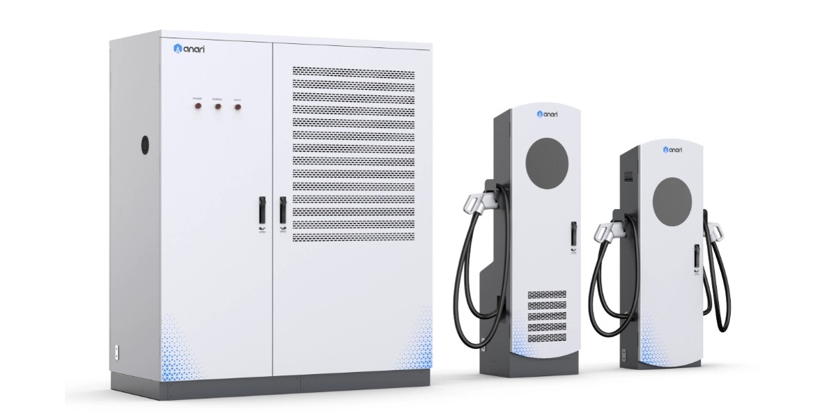
High-Voltage 1000V Split DC Systems: Powering the Next Generation of EV Superchargers
Meta description: What 1,000V DC capability means for split EV charging systems in 2026 — wide-range output, constant-power windows, insulation coordination, and how to avoid stranding capital on 400V-era hardware.
Quick Answer
A 1,000V split DC system is a charging architecture whose power cabinets deliver a DC output range spanning roughly 150V to 1,000V, feeding remote dispensers through a shared DC bus. The high ceiling matters because next-generation passenger EVs, light commercial vehicles, and heavy trucks use 800V and 1,000V-class battery packs; at 1,000V, a charger delivers high power at half the current of a 500V system, which halves cable heating and enables lighter, liquid-cooled connectors. In a split layout, the cabinets convert and control that voltage centrally while slim dispensers stay at the bay. For operators in 2026, the decision is not whether to buy 1,000V hardware, but whether the hardware’s whole output window — not just its peak voltage — can serve the mixed 400V, 800V, and 1,000V fleets arriving on site simultaneously.
Key Takeaways
- Voltage is the lever that lowers current. Moving from 500V to 1,000V halves the current for the same power, which cuts conductor losses and cable mass — the core reason high-voltage platforms exist.
- A wide constant-power window matters more than the headline voltage. Vehicles only accept peak power across a limited state-of-charge range, so the charger must hold full power across the widest possible voltage band.
- Mixed fleets are the real test. Sites in 2026 serve 400V cars, 800V cars, and 1,000V trucks in the same hour; only genuinely wide-range output avoids derating or extra DC-DC stages.
- Insulation and protection scale with voltage. Creepage, clearance, and isolation ratings, plus IEC/UL compliance, must be confirmed at 1,000V — not extrapolated from 500V test data.
- Split architecture absorbs voltage transitions. Cabinets are replaced or expanded over a decade while dispensers, trenching, and civil works remain — exactly the right place to hold technical risk.
From 400V to 1,000V: Why the Automotive Industry Moved
Battery voltage rises because current is expensive. For a given charging power, current and voltage trade off directly (P = V × I). A 250kW session at 400V requires roughly 625A; at 800V it requires about 313A; at 1,000V it requires about 250A. Lower current means thinner conductors, smaller contact areas, less resistive heating, and cables that a person can physically handle without cooling overhead.
The automotive market has followed that logic in two waves. First, 800V architectures entered premium passenger vehicles and commercial vehicles, letting them accept 250–350kW over CCS2 without impractical cable mass. Now, 1,000V-class platforms are arriving for vehicles that need 400kW+ per lane — high-end cars, electric light commercial fleets, and heavy-duty trucks operating on gigawatt-hour duty cycles.
The infrastructure consequence is immediate. A charger rated only to 500V or 600V output cannot serve these vehicles at their design power, and in some cases cannot charge them at all without an external DC-DC converter. Meanwhile, 400V vehicles remain a large share of the installed fleet for years to come. The result is that high-quality charging hardware in 2026 must be wide-range rather than high-voltage-only.
| Vehicle Platform | Typical Pack Voltage | Typical Peak Acceptance | Current at Peak (approx.) | Charger Requirement |
|---|---|---|---|---|
| Legacy passenger EV (400V class) | 350–450V | 50–150kW | 125–375A | Output floor below 200V |
| Modern passenger EV (800V class) | 700–800V | 150–350kW | 190–440A | 150–1,000V wide range |
| Next-gen passenger EV (1,000V class) | 900–1,000V | 250–500kW | 250–500A | 1,000V-capable, cooled cable |
| Electric light commercial | 600–800V | 100–250kW | 125–315A | Wide range, dual-standard dispenser |
| Heavy truck / bus (megawatt-ready) | 800–1,250V | 400–1,200kW | 400–1,000A+ | 1,000V+ output, liquid-cooled |
Read this table as a compatibility statement, not an electrical one. Any site expected to serve three or more of these vehicle classes needs cabinets whose output window spans the entire range — and a dispenser strategy that handles CCS1, CCS2, NACS, and GB/T without adapter friction.
The Constant-Power Window: The Specification Buyers Should Interrogate
Chargers are marketed with peak power, but vehicles experience the constant-power window. Batteries accept full current only within a voltage band — typically from around 20–30% state of charge to 50–60%. Outside that band, current limits or thermal limits reduce power. A charger that holds full output from 200V to 1,000V will deliver more total energy per session than one that holds full output only from 600V to 1,000V, even if both are rated 480kW.
Three parameters define real capability:
- Minimum output voltage — determines whether 400V vehicles can access full power without a converter stage.
- Maximum output voltage — determines whether 1,000V platforms can reach their design power.
- Current limit across the window — a constant-current ceiling that applies below the constant-power region.
Engineering the wide window is a design challenge: it requires power modules with broad output regulation, transformer ratios that avoid extreme duty cycles at both ends, and control loops that keep efficiency high across a 5:1 voltage span. That is why not all “1,000V-ready” chargers behave alike in the field.
Why Split Architecture Handles Voltage Transitions Better
Voltage standards evolve faster than civil infrastructure, so it pays to put the volatile part in the replaceable part of the system. In a split design:
- Power cabinets contain the modules that define voltage and current capability. Upgrading to a higher-voltage module generation means swapping modules or adding cabinets in one electrical room.
- Dispensers contain the cable, connector, interface, and metering. They are replaced when a new connector standard emerges, at a fraction of the cost of station replacement.
- Civil works, trenching, transformers, and switchgear are effectively permanent and unaffected by the voltage generation they serve, provided they are sized for the site’s final target on day one.
Compare this with integrated chargers, where the voltage capability, connector, power stage, and enclosure are inseparable. When the fleet moves from 800V to 1,000V, an integrated station’s only upgrade path is replacement — including civil works, permits, and re-energization.
Engineering Details That Decide 1,000V Reliability
Higher voltage changes failure modes, not just ratings. Four engineering areas require explicit attention in procurement:
| Engineering Area | 500–600V Design Practice | 1,000V Design Requirement |
|---|---|---|
| Insulation coordination | Creepage/clearance per LV practice | Reinforced insulation, pollution degree 2, altitude-corrected |
| Switching devices | Silicon IGBTs, moderate switching loss | SiC MOSFETs for lower loss and faster switching |
| Connector contact design | Air-cooled, 200–400A typical | Liquid-cooled, 500–1,000A+, temperature-monitored |
| Cable construction | Large copper cross-section | Cooled jacket, conductor cross-section reduced 40–60% |
| Protection and isolation | Standard DC breakers | DC-rated devices for 1,000V, arc-fault detection |
| Compliance evidence | IEC 61851-23 baseline | IEC 61851-23 plus UL 2202 / TUV testing at full voltage |
Ask for test reports at operating voltage, not design intent. A verified 1,000V DC test certificate from a recognised body such as TUV or UL is the only reliable evidence that isolation, creepage, and thermal design are adequate. Certificates that reference a 500V variant of the same platform should be treated as a different product.
Site-Level Implications of 1,000V Fleets
Higher-voltage vehicles shift constraints from the cable to the grid. At 1,000V working voltage, a 480kW lane draws roughly 480A at the DC output but still requires the same AC-side power; site electrical design does not change. What does change is:
- Simultaneity risk. High-voltage vehicles accept more power for longer, so more lanes hit peak draw at once. Dynamic power sharing and site-limit control become essential rather than optional.
- Transformer sizing. Sites serving 1,000V trucks typically provision 1,000–2,500kVA with room for growth, frequently paired with battery storage to cap peaks.
- Cooling plant capacity. Cooled cables and modules reject more heat when operated continuously; the power room’s thermal design must handle sustained full-load operation in summer ambient, not just intermittent peaks.
Operators who plan the grid connection for their final voltage generation avoid the most expensive retrofit of all — a utility capacity upgrade.
Choosing Hardware: A Short Selection Framework
Match the charger to the fleet you will have in 2028, not the fleet you have today. A practical framework:
- Confirm the output window, not the peak rating. Require documented full-power operation from below 200V to 1,000V DC.
- Confirm current capability over time, not instantaneously. Sustained current at design ambient is the meaningful number.
- Confirm connector and cable cooling. Above 400A, liquid-cooled cables are the only ergonomic option; specify cooling and monitoring.
- Confirm module granularity. 40kW or 60kW hot-swappable modules allow capacity and voltage upgrades without cabinet replacement.
- Confirm protocol and standards support. OCPP 2.0.1, ISO 15118 Plug & Charge, and CCS1/CCS2/NACS/GB/T connector options keep the site interoperable.
- Confirm certification at voltage. TUV, CE, and UL evidence at 1,000V DC for the target market.
MIDA’s High-Voltage Split Portfolio
MIDA Power engineers its DC platform around wide-range output and modular capacity. Its 40kW/60kW liquid-cooling power modules support the wide DC output window that lets a single cabinet serve 400V cars, 800V platforms, and 1,000V next-generation vehicles, and they are designed for hot-swap replacement so a voltage-generation upgrade becomes a module change rather than a site rebuild.
The same platform appears across product lines: attended hubs can deploy the 360kW liquid-cooled station with RFID, OCPP and POS, while motorway-grade duty is demonstrated by the 480kW liquid-cooled ultra-fast charging station. Split configurations scale from 240kW to 1,440kW on the same architecture, with TUV/CE/UL certification and OCPP 2.0.1 support. Buyers planning high-voltage corridors and depots can review the full commercial DC fast charging range to align cabinet voltage, dispenser count, and connector mix with their fleet roadmap.
FAQ
1. What does “1,000V split DC system” actually mean?
It means the power cabinets deliver DC output up to 1,000V and feed remote dispensers over a shared bus. The dispensers carry the cooled cable and connector; the cabinets hold the rectifier modules, switching, and cooling that define voltage and current capability.
2. Can a 1,000V charger still charge a 400V car?
Only if its output window extends low enough — typically below 200V — and if it can hold useful current at that voltage. Wide-range modules handle both. A narrow high-voltage-only design may require an external DC-DC converter or deliver reduced power to 400V vehicles.
3. Why does 1,000V matter if the power rating is the same?
Because current halves for the same power, cutting resistive losses and cable mass. That makes higher connector currents physically manageable and lets vehicles accept more power without adding heavy copper or oversized cooling.
4. Is 1,000V output dangerous for maintenance staff?
It requires the same disciplined approach as any DC fast charging equipment: isolation, lockout/tagout, voltage verification, and insulated tooling. The design obligation is on the manufacturer — reinforced insulation, adequate creepage and clearance, DC-rated protective devices, and certified test evidence at full operating voltage.
5. Do I need liquid-cooled cables at 1,000V?
Not for voltage reasons alone, but for current. Above roughly 400–500A sustained, cooled cables are required for ergonomics and thermal control. Most 1,000V deployments above 350kW per lane use them.
6. Will 1,000V systems make 800V chargers obsolete?
No. Wide-range systems supersede narrow-window designs rather than any specific voltage class. The practical obsolescence risk belongs to chargers that cannot serve both 400V and 1,000V vehicles from the same cabinet.
7. How should I phase investment across 400V, 800V, and 1,000V fleets?
Buy wide-range cabinets now, size transformer and civil works for the final 1,000V+ target, and add modules or cabinets as the vehicle mix shifts. Dispensers can be replaced independently, which keeps the expensive, permanent parts of the site unaffected by voltage transitions.
Conclusion
High-voltage charging is a current-management story told in volts. Moving to 1,000V lets a system deliver more power through lighter, cooler, more manageable hardware — but only if the charger’s entire output window, not just its ceiling, serves the mixed fleets on site. Split architecture places the volatile part of that equation — modules and dispensers — where it can be replaced economically, while the permanent parts of the site are built once. Specify wide-range output, certified 1,000V evidence, and modular expansion, and the next generation of EV supercharging becomes an upgrade path rather than a rebuild.
Post time: Sep-17-2026


