
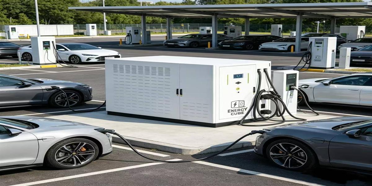
MIDA 40kW DC-Coupled Solar Charging: Minimizing Conversion Loss for Fleets
Quick Answer
A 40kW DC-coupled solar charging unit delivers solar energy to a fleet vehicle through one or two conversion stages instead of four, which raises PV-to-vehicle efficiency to 93–96% compared with 84–88% for an AC-coupled equivalent. On a depot moving 200,000 kWh per year, that gap equals roughly 16,000–24,000 kWh of generation the site no longer has to buy, or 4–7 kWp of additional array capacity it does not have to install. For fleets, the 40 kW rating is the operative sweet spot: it charges a light commercial van’s 60–90 kWh pack in 90–150 minutes during a shift or work break, it matches real-world dwell patterns rather than theoretical peak power, and it can be deployed in multiples from a single PV array and storage block.
Key Takeaways
- DC coupling removes two conversion stages — the PV inverter and the charger’s AC rectifier — cutting losses from 12–16% to 4–7% between array and vehicle battery.
- 40 kW matches fleet dwell time. Opportunity charging during a 90–150 minute break covers most light commercial duty cycles without needing 150 kW+ hardware.
- Loss reduction is capital avoidance. Every percentage point of efficiency recovered reduces required array size, storage capacity, and energy purchases simultaneously.
- Fleet economics favour DC-coupled depots: $0.07–$0.12 per delivered kWh versus $0.19–$0.28 for grid-only charging, with payback in 3.5–5.5 years.
- Modular deployment is the scaling strategy: start with two 40 kW units on one DC bus, add units, storage, and PV strings as the fleet electrifies.

Why Conversion Loss Matters More Than It Sounds
Fleet operators are used to thinking in cost per kilometre and cost per kilowatt-hour. Conversion losses are usually treated as an engineering footnote, a few percentage points absorbed into the business case. At depot scale, that assumption is wrong, because losses compound three times over.
First, losses are paid twice — once in generation and once in purchase. Every kWh lost between the array and the vehicle battery must be replaced. If the site covers 70% of its energy from PV and purchases the remainder, the replacement energy arrives at retail tariff, not at solar cost. A 10-percentage-point loss therefore costs considerably more than 10% of the solar output.
Second, losses drive capital sizing. A site requiring 200,000 kWh per year of delivered energy at 86% PV-to-vehicle efficiency needs a larger array, a larger battery, and larger converters than the same site at 95% efficiency. The difference is 20–25 kWp of array and 25–40 kWh of storage — capital that sits on the balance sheet for a decade.
Third, losses generate heat. Heat in the power conversion stage forces derating at high ambient temperature and shortens component life. On a depot in a warm climate, an inefficient conversion chain converts directly into reduced availability during the hours when vehicles need charging most.
The following table isolates the conversion chain, stage by stage, for the same 100 kWh of PV generation delivered to a vehicle battery.
| Stage | AC-coupled DC charger | DC-coupled solar charger | Notes |
|---|---|---|---|
| PV DC to PV inverter | 97.5% | — | Stage eliminated in DC coupling |
| PV inverter to AC bus | — | — | 98% including transformer and cabling |
| MPPT / DC/DC PV conversion | — | 98.5% | Single stage to DC bus |
| DC bus distribution | — | 99.5% | Low-loss at 1,000–1,500 V |
| Battery bidirectional conversion (charge) | 96.0% (AC/DC) | 98.0% (DC/DC) | DC/DC avoids double conversion |
| Battery bidirectional conversion (discharge) | 96.0% | 98.0% | |
| Charger AC/DC rectification | 95.5% | — | Stage eliminated in DC coupling |
| Charger DC/DC output regulation | 97.5% | 97.5% | Common to both architectures |
| Cable and connector losses | 1.0% | 1.0% | Liquid-cooled cables reduce this further |
| PV-to-vehicle efficiency | ≈ 84–88% | ≈ 93–96% | 8–10 percentage points recovered |
| Energy delivered from 100 kWh generated | 84–88 kWh | 93–96 kWh |
On a depot generating 300 MWh of solar annually, that difference is 24–30 MWh per year — the annual driving energy of roughly 120–150 light commercial vehicles at typical efficiency.

Why 40 kW Is the Right Rating for Fleet Depots
Charging hardware is frequently over-specified because peak power is easier to market than energy delivered. Fleets buy availability and turnaround, not kilowatts. A light commercial van with a 70 kWh usable pack covering 150–200 km per day in urban service needs about 90 minutes at 40 kW to restore that day’s energy — neatly inside the loading, lunch, or shift-change window that already exists at the depot. Providing 150 kW would shorten the session to 25 minutes but requires a service upgrade, a larger converter, and thicker cabling: capital deployed against a constraint the fleet does not have.
| Fleet vehicle class | Usable pack | Daily energy need | Time at 40 kW | Fit to depot routine |
|---|---|---|---|---|
| Urban delivery van | 50–70 kWh | 60–90 kWh | 90–135 min | Loading dock window |
| Light commercial pickup | 70–90 kWh | 70–100 kWh | 105–150 min | Shift change or lunch break |
| Municipal service vehicle | 60–80 kWh | 50–80 kWh | 75–120 min | Between work orders |
| Last-mile cargo van | 40–60 kWh | 45–70 kWh | 70–105 min | Mid-shift top-up |
| Yard or shuttle vehicle | 30–60 kWh | 40–70 kWh | 60–105 min | Continuous rotation |
| Heavy-duty truck / bus | 300–600 kWh | 250–450 kWh | not viable at 40 kW | Requires 240 kW+ liquid-cooled systems |
The last row is the boundary condition. Where a fleet includes heavy-duty vehicles, the architecture changes: those vehicles require the 600kW–720kW liquid-cooled DC charging station for EV trucks and buses, which uses the same wide-voltage module philosophy at a much higher output class. For light and medium commercial fleets, 40 kW DC-coupled units deliver the required energy at the lowest capital and operating cost per delivered kWh.
Depot Architecture: How 40 kW Units Fit a DC Bus
A fleet depot is best designed as a shared-energy, distributed-output system rather than a collection of independent chargers.
- One PV array. Sized to the depot’s annual energy requirement rather than to peak charging power. For a 10-vehicle fleet covering 180 km per vehicle per day, the annual energy need is roughly 400 MWh, implying 300–400 kWp in a moderate-irradiance location — often more than the depot roof or yard can host, which is why DC coupling matters: it extracts 8–10% more usable energy from the same array.
- One storage block. Sized at 0.5–1.0 times the daily charging energy for a shift-based depot, or 1.0–1.5 times for a depot with evening returns. Storage serves three functions: it shifts midday solar into the evening charging window, it caps the site’s peak import during simultaneous sessions, and it maintains charging availability during grid events.
- One DC bus at 1,000–1,500 V. PV, storage, and all charging units connect here. Higher bus voltage reduces current, cable cross-section, and resistive loss across the depot — material savings on a site with 100+ metres of feeder run between the storage container and the charging bays.
- Multiple 40 kW charging units. Distributed to the bays where vehicles park. Each unit contains two to three wide-voltage charging modules, the same EV charging module technology used across MIDA’s DC product families, so a module fault reduces output rather than removing a bay from service.
- One fleet EMS. Schedules charging by departure time, tariff band, and state of charge; verifies that each vehicle leaves with the required energy; and reports energy, cost, and exceptions per vehicle and per driver.
The result is a depot where the expensive parts — array, storage, bus, and controller — are purchased once and shared, while the charging hardware scales in 40 kW increments as the fleet electrifies. That modularity is the difference between a capital programme that can be staged over three budget years and one that must be approved as a single event.
Efficiency Economics: What the Loss Reduction Is Worth
The table below compares two identical depots — 10 light commercial vehicles, 400 MWh annual charging energy — built with different coupling architectures.
| Metric | AC-coupled depot | DC-coupled 40 kW depot |
|---|---|---|
| PV array required | 400 kWp | 360 kWp |
| Storage installed | 400 kWh | 350 kWh |
| Conversion stages PV→vehicle | 4 | 1–2 |
| PV-to-vehicle efficiency | 86% | 95% |
| Annual PV generation | 440 MWh | 396 MWh |
| Annual purchased energy | 56 MWh | 20 MWh |
| Installed capex | $415,000 | $368,000 |
| Annual energy cost | $13,400 | $4,600 |
| Annual O&M | $14,500 | $10,700 |
| Simple payback | 7.4 years | 5.1 years |
| 10-year cost per delivered kWh | $0.121 | $0.093 |
The DC-coupled depot wins on every line, and the mechanism is not price negotiation — it is 9 percentage points of recovered conversion efficiency applied three times: to array sizing, to storage sizing, and to purchased energy. That is what “minimising conversion loss” is worth in practice, and it is why the architecture decision precedes every other procurement question.
Design Details That Protect Fleet Depot Performance
Module granularity and voltage window. Each 40 kW unit should use two to three independent 20 kW-class modules with output spanning 200–1,000 V DC. This serves 400 V and 800 V vehicle architectures at full power and preserves partial availability if a module faults.
Liquid cooling at the power stage and cable. Depot bays are often canopy-shaded but the power conversion cabinets are not. Liquid-cooled modules and cables sustain rated output at 45–50°C ambient, while air-cooled designs derate exactly when midday solar output peaks.
Storage converter power at 80–100% of aggregate charging power. A 10-bay depot with 400 kW of aggregate charging capability needs a converter rating in the 320–400 kW range, or a scheduling strategy that guarantees fewer than all bays run simultaneously, otherwise the battery cannot support peak sessions and the site imports at its worst tariff.
Wide-temperature and dust-rated enclosures. Depots are industrial environments. IP54 enclosures, filtered ventilation for any air-cooled auxiliary equipment, and vibration-tolerant mounting are baseline requirements, not options.
Plug & Charge and scheduling integration. ISO 15118 enables automatic authentication and billing per vehicle, while OCPP 2.0.1 lets the depot’s fleet management system set the required departure state of charge. Without both, charging scheduling becomes a manual process that erodes the labour savings quoted in the business case.
Protection and isolation on the DC bus. Arc-fault detection, insulation monitoring, coordinated DC isolation, and rapid shutdown provisions are mandatory for a shared bus serving multiple bays. Documentation should be delivered with the equipment, not provided after commissioning.
Metering and per-vehicle reporting. Revenue-grade metering at each output feeds energy accounting, carbon reporting, and driver reimbursement. For fleets reporting scope 1 and scope 2 emissions, this data is a compliance requirement, not an optional feature.
Deployment Roadmap for a Solar-Coupled Fleet Depot
| Phase | Duration | Key activities |
|---|---|---|
| Fleet and route analysis | 2–4 weeks | Duty cycles, dwell windows, energy per vehicle per day, depot capacity limits |
| Sizing and financial model | 2–3 weeks | Array and storage sizing, tariff analysis, payback model, staged investment plan |
| Design and permitting | 6–10 weeks | Single-line diagrams, protection study, structural review for canopy or roof |
| Equipment manufacture | 8–14 weeks | Charging units, storage, PV, and EMS configured and factory-tested |
| Installation and commissioning | 3–6 weeks | Civil works, DC bus installation, charging unit mounting, energisation, islanding test |
| Optimisation and handover | 4–8 weeks | Dispatch tuning against real data, driver workflow integration, training |
A staged rollout is usually the correct commercial structure: install the shared infrastructure (array, storage, DC bus, EMS) sized for the full fleet, then deploy 40 kW charging units in tranches as vehicles are delivered. This avoids paying for charging capacity before the vehicles exist while keeping the high-cost shared elements at final scale from the outset.
Procurement Checklist for DC-Coupled Fleet Charging
- Require stage-by-stage efficiency data, not a single headline number. Ask for PV-to-vehicle efficiency at the bus level, including storage round trip.
- Specify wide-voltage modules (200–1,000 V, 1,500 V-class where heavy-duty vehicles are planned) and confirm simultaneous-session power sharing behaviour.
- Demand ≥80% converter-to-charger power matching so storage can support actual depot peak sessions.
- Insist on module-level redundancy with field-replaceable units and stated mean time to repair.
- Verify certifications for storage (IEC 62619; UL 9540/9540A where applicable), charging interface (IEC 61851, IEC 62196), and communication (OCPP 2.0.1, ISO 15118).
- Ask for a 10-year degradation and augmentation plan with pricing, so capacity retention is a contractual commitment rather than a modelling assumption.
- Confirm islanding and resilience behaviour if depot operations cannot tolerate grid outage downtime.
- Check the service footprint — response time, spares holding, and remote diagnostics capability in your region.
How MIDA Supports Fleet-Scale DC-Coupled Deployments
MIDA Power manufactures the components a DC-coupled fleet depot is built from, under one engineering organisation: wide-voltage charging modules, DC charging cabinets and units from 40 kW to 240 kW, storage integration, and PV components. That single-source structure matters most at the system boundary — where the EMS needs to command PV conversion, battery discharge, and charging output on one bus. The architecture used in MIDA’s integrated zero-emission reference project, the 200kWh solar BESS EV charging station, applies directly to fleet depots at the 40 kW unit level. Operators planning mixed fleets can review the full MIDA charging portfolio for connector options (CCS1, CCS2, NACS, GB/T), portable and AC products for support vehicles, and the 600kW–720kW liquid-cooled DC charging station for EV trucks and buses where heavy-duty vehicles join the fleet.
FAQ
1. How much more efficient is DC-coupled charging than AC-coupled charging?
Measured from PV array to vehicle battery, DC coupling typically achieves 93–96% efficiency versus 84–88% for AC coupling. The difference comes from eliminating the PV inverter and the charger’s AC rectifier, plus replacing AC/DC battery conversion with DC/DC.
2. Is 40 kW enough to charge a commercial fleet vehicle?
For light and medium commercial vehicles with 40–90 kWh packs, yes. A 70 kWh van that needs 150–200 km of range per day is fully replenished in 90–150 minutes at 40 kW, which fits inside existing depot dwell windows. Heavy-duty trucks and buses require 240 kW and above.
3. How do I decide between distributed 40 kW units and one large central charger?
Distributed units match depot dwell patterns and avoid concentrating risk; a central high-power charger makes sense only when vehicles must turn around in under 30 minutes or when heavy-duty vehicles are involved. Most light-fleet depots are better served by multiple 40 kW units on a shared DC bus.
4. How much storage should a 40 kW solar fleet depot include?
Plan on 0.5–1.0 kWh of usable storage per kWh of daily charging energy for shift-based depots, and 1.0–1.5 kWh per kWh for depots with evening returns. Converter power should be 80–100% of aggregate charging power to support simultaneous sessions.
5. What is the typical payback for a DC-coupled solar fleet depot?
For a 10-vehicle depot with 250–400 MWh of annual charging energy, simple payback typically falls between 3.5 and 5.5 years without incentives, and 2.5–3.5 years with them. Fleet depots usually outperform public charging sites because utilisation is predictable and high.
6. Can these units charge different connector types and vehicle brands?
Yes, provided the charging unit is specified with the right connector portfolio — CCS1, CCS2, NACS, GB/T, or CHAdeMO as required by the fleet. Wide-voltage output (200–1,000 V DC) ensures full power across 400 V and 800 V vehicle architectures.
7. How much maintenance does a DC-coupled solar depot require?
Plan for quarterly PV cleaning and inspection, annual thermographic inspection of DC busbars and terminations, semi-annual battery state-of-health reporting, coolant and filter checks on liquid-cooled cabinets, and periodic connector inspection at high-cycle bays. Remote monitoring typically resolves the majority of reported issues without a site visit.
Post time: Sep-15-2026


