
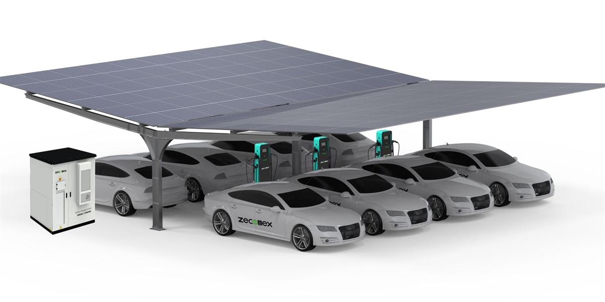
Overcoming Grid Constraints: Integrating BESS with Modular Split DC Charging Stacks
Quick Answer
Grid constraints — a limited service connection, an expensive upgrade, or a multi-year queue for reinforcement — no longer have to cap a charging site’s power. Integrating a Battery Energy Storage System (BESS) with modular split DC charging stacks decouples the site’s delivered charging power from its grid import limit: the battery acts as a buffer that absorbs cheap or surplus energy when the site is idle and discharges it into the charging peak, so a site can offer 480–960kW of fast charging from a 200–300kW grid connection. Because the split DC architecture separates power cabinets from dispensers and exposes a common DC bus, the battery can be DC-coupled directly to the charging stack, avoiding an extra conversion stage and improving round-trip efficiency by roughly 3–5%. In practice, BESS-buffered modular hubs achieve 30–50% demand-charge reduction, install on a 25–40% smaller connection, and reach service months or years earlier than sites waiting on grid reinforcement — which in 2026 is often the deciding factor in whether a project proceeds at all.
Key Takeaways
- The grid, not the charger, is the binding constraint. Connection capacity, upgrade cost, and reinforcement lead time — not equipment availability — decide where and when high-power hubs can be built.
- BESS turns a hard grid limit into a soft one. A battery-sized buffer lets a site deliver several times its import capacity during peak charging windows.
- Modular split stacks are the ideal host for storage. Centralised power cabinets and an exposed DC bus make DC-coupled storage simpler and more efficient than retrofitting storage onto monolithic chargers.
- DC coupling beats AC coupling on efficiency. Removing one conversion stage in each direction saves roughly 3–5% round-trip, worth thousands of euros a year on a daily-cycled battery.
- The economics ride on three mechanisms. Peak shaving, energy arbitrage, and grid-service revenue each attack a different cost or income line, and together they usually fund the battery.
The Grid Is the Real Bottleneck
Ask any hub developer what delays a project and the answer is rarely the chargers. It is the grid. A site with an appealing location and strong traffic may be served by a feeder that cannot supply the 500kW or 1MW the charging business needs. The developer then faces a familiar menu of bad options:
- Pay for reinforcement. Capacity upgrades can cost from tens of thousands to millions, with costs often borne largely by the developer.
- Wait. High-voltage reinforcement queues routinely run 12–36 months, and in some markets longer.
- Cap the site. Design to the existing connection, accept lower peak power, longer sessions, and queuing at busy hours.
Each option has a cost: capital, time, or lost revenue. And each is avoidable if the site stops trying to draw its peak charging power from the grid at all.
The insight behind BESS-integrated charging is that a charging site’s problem is not energy, it is power at a moment. Charging demand is spiky: a hub may pull 600kW for two hours in the evening and 50kW the rest of the day. A grid connection must be sized for the peak; a battery only needs to cover the gap between the peak and the connection limit, for the duration of the peak. That gap is usually far smaller than the peak itself.
Why Modular Split Stacks Are the Right Host for Storage
Storage can be bolted onto almost any charger, but the quality of the integration depends heavily on the charging architecture. This is where modular split DC stacks have a structural advantage.
A split stack centralises AC-to-DC conversion in power cabinets and delivers DC to slim dispensers through a shared bus. That shared DC bus is the natural coupling point for a battery: the BESS connects at the same DC node the cabinets feed, so energy flows between battery, cabinets, and dispensers without repeatedly converting between AC and DC. The modular nature of the stack — cabinets built from hot-swappable 40kW/60kW liquid-cooling power modules — also means the site can be grown in discrete increments that match both the battery’s capacity and the site’s proven demand.
By contrast, an all-in-one charger usually presents only an AC interface, so storage must be AC-coupled, adding a conversion step in both directions and eroding round-trip efficiency. Retrofitting DC coupling onto monolithic hardware is often impossible without replacing the charger.
Sizing the Triad: Stacks, Battery, and Grid
The design task is to size three elements together: the charging stacks, the battery, and the grid connection. The generator of demand is the stack cluster; the buffer is the battery; the floor is the grid limit.
| Site Class | Charging Capacity | Grid Connection | BESS Usable Capacity | Peak Delivery | Typical Use Case |
|---|---|---|---|---|---|
| Constrained urban | 240kW, 2–4 stalls | 100–150kW | 150–250kWh | 240kW | Retail, hotel, small depot |
| Mid-size hub | 480kW, 4–8 stalls | 200–300kW | 300–600kWh | 480kW | Mixed public/fleet |
| Large hub | 960kW, 8–16 stalls | 400–600kW | 600–1,200kWh | 960kW | Corridor plaza, logistics park |
| Corridor megasite | 1,440kW+, 16–24 stalls | 600–1,000kW | 1,000–2,000kWh | 1,440kW+ | Motorway, regional super hub |
Two rules keep sizing sensible. First, size the battery to the grid gap, not to the station: compute the delta between peak concurrent charging demand and the contracted grid capacity, then multiply by the duration of a realistic peak event. Second, size the stack to concurrent demand, not to the sum of dispenser ratings: with dynamic power sharing, total delivered power never exceeds the cabinets’ combined rating, so the stack can be smaller than the sum of what the dispensers could theoretically draw.
The Three Economic Mechanisms
A battery is not free, so its value must be demonstrated. Three mechanisms carry the business case.
1. Peak shaving. The battery covers everything above the contracted capacity, so the site’s monthly peak demand — and its demand charge — is set by design rather than by the worst simultaneous session of the month. On high-demand-tariff markets, this alone can be worth tens of thousands per year.
2. Energy arbitrage. The battery buys or stores energy when it is cheap — overnight off-peak power, or surplus solar at midday — and discharges it into the evening charging peak. On a site that already owns generation, this converts curtailment or low-value export into premium retail energy.
3. Grid services. Where flexibility markets exist, the battery’s spare capacity earns frequency regulation, capacity, or demand-response payments, all while the charging business continues unaffected because grid-service discharge is absorbed by the battery rather than by a vehicle.
| Mechanism | Timescale | Where It Helps | Relative Contribution |
|---|---|---|---|
| Peak shaving | Monthly | Demand charges | High in high-tariff markets |
| Energy arbitrage | Daily | Energy cost per kWh | Moderate to high |
| Grid services | Seconds to hours | New revenue | Variable by market |
| Connection deferral | Once, at build | Capex and lead time | Very high where queues are long |
Coupling Options: DC Versus AC
| Design Choice | DC-Coupled BESS | AC-Coupled BESS |
|---|---|---|
| Conversion stages | Fewer (direct DC bus) | More (extra AC/DC each way) |
| Round-trip efficiency | Higher (roughly +3–5%) | Lower |
| Best host | Split DC stacks with exposed DC bus | Monolithic AC chargers |
| Retrofit feasibility | Requires DC bus access | Possible on most AC chargers |
| Grid interaction | Through the cabinets’ front end | Through the battery’s own inverter |
| Typical fit | New-build modular hubs | Legacy AC-limited sites |
DC coupling is the higher-efficiency choice and the natural fit for modular split stacks, which expose the DC bus by design. AC coupling remains a valid option — and sometimes the only option — for sites anchored on legacy monolithic hardware.
Control, Standards, and the EMS
Storage-integrated charging is a control problem as much as a hardware one. The site energy management system must arbitrate between grid import, battery charge/discharge, and dispenser demand in real time, while staying inside the connection limit and the battery’s own constraints.
The practical requirements are:
- OCPP 2.0.1 smart charging with signed transactions and charging profiles, so dispenser demand can be shaped dynamically.
- ISO 15118 for Plug & Charge, which removes authentication friction at high-traffic sites.
- Grid-code compliance for export control and interconnection — for example VDE-AR-N 4105 in Germany or Rule 21 in California — plus, in the US, IEEE 1547-conformant interconnection for the storage interface.
- Battery safety and fire compliance per UL 9540/NFPA 855 or local equivalents.
Specifying these on day one is nearly free; retrofitting them onto legacy hardware is expensive. MIDA’s commercial platforms ship protocol-complete across the commercial DC fast charging range, which keeps the control plane consistent as storage and stacks are added.
A Representative Deployment
Consider a logistics park with a 250kW grid connection — enough for offices and lighting, nowhere near enough for fast charging. The design pairs two 240kW split cabinets (480kW total) with a 500kWh DC-coupled BESS. During the day, the battery tops up on cheap capacity; in the evening peak, it discharges alongside the grid to deliver the full 480kW to four trucks at once. Overnight, it refills. The site never exceeds its 250kW import limit, so no upgrade is required, the demand charge stays modest, and the project proceeds without waiting in a reinforcement queue. The cabinets themselves can later be extended to 960kW by adding modules and cabinets, with the battery resized against the new peak — an expansion path that reuses the original grid connection.
How MIDA Fits the Grid-Constrained Site
MIDA Power builds the two layers this architecture needs: the modular charging stack and the component foundation for storage-integrated operation. The 40kW/60kW liquid-cooling power modules are the building blocks of every cabinet, sized precisely to a site’s power zone and expandable in discrete increments. For attended hubs, the 360kW liquid-cooled charging station with RFID, OCPP, and POS shows the full-service configuration, while the 480kW ultra-fast liquid-cooled station for motorways demonstrates the same platform under sustained high-power corridor duty. Because the split architecture exposes a common DC bus, it gives the storage integrator the coupling point that makes DC-coupled BESS practical.
FAQ
1. How large a BESS do I need to support a 480kW charging hub?
Most 480kW hubs on a constrained connection land between 300kWh and 600kWh of usable capacity. Size it by the gap between peak charging demand and the contracted grid capacity, multiplied by the duration of the evening peak.
2. Can a BESS let me charge faster than my grid connection?
Yes. The battery discharges into the peak alongside the grid, so the site can deliver substantially more charging power than its import limit — often two to three times the connection rating for the duration of the buffer.
3. Is DC coupling always better than AC coupling?
DC coupling is more efficient, typically by 3–5% round-trip, and is the natural fit for split DC stacks that expose a common DC bus. AC coupling remains valid where the chargers only present an AC interface.
4. Does a battery reduce my demand charges automatically?
Only with the right control logic. The EMS must actively cap grid import and cover the excess from the battery; without that, the battery does not protect the demand charge.
5. What happens to charging during a grid outage?
With islanding capability, a BESS can keep a defined number of dispensers energised, which is valuable for emergency and municipal resilience. Confirm islanding and backup behaviour during design, as it affects transfer equipment and protection settings.
6. Will storage compliance add significant cost or delay?
It adds a compliance workstream — typically UL 9540/NFPA 855 or local fire and battery codes — but specifying it during design keeps cost and schedule impact modest. A single vendor for the charging stack collapses several interfaces into one file.
7. Does the battery complicate future expansion?
No, if the architecture is modular. Adding cabinets reuses the same DC bus and grid connection; the battery is simply resized against the new peak. This is precisely why storage integration pairs best with modular split stacks rather than monolithic hardware.
The Bottom Line
Grid constraints are the most common reason a strong charging site never gets built. A BESS integrated with modular split DC stacks dissolves that constraint: the battery absorbs the mismatch between spiky charging demand and a modest connection, so the site delivers 480–960kW of service from a 200–300kW feed, shaves demand charges, arbitrages energy, and reaches operation without waiting for grid reinforcement. Because split stacks expose a common DC bus, the battery couples directly and efficiently, and the modular hardware lets both capacity and storage grow in steps that follow demand. For developers facing a weak or expensive connection in 2026, the pairing of BESS and modular split DC charging is not a workaround — it is the design that makes the site viable in the first place.
Post time: Sep-17-2026


