
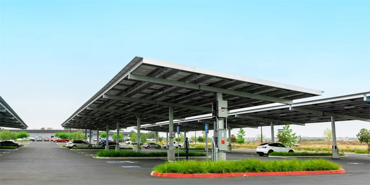
Strategic Site Planning: Where to Place Split DC Cabinets for Maximum Efficiency
Quick Answer
In a split DC charging site, the power cabinets should be placed in a dedicated, protected utility zone — a plant room, service corridor, or purpose-built enclosure — located as close to the incoming transformer as practical, typically 30–150 metres from the dispensers, on ground level above flood risk, with provisioned ventilation, service clearance, and cable routing sized for the site’s final capacity. The correct placement is not a cosmetic decision: cabinet location sets the length and therefore the cost, voltage drop, and thermal performance of every dispenser run, determines whether the site can be expanded without new civil works, and decides whether maintenance can be performed safely and quickly. Good placement concentrates the heavy electrical and thermal load in one serviced area and keeps driver-facing hardware simple; poor placement forces long, hot, expensive cable runs and turns every future stall into a construction project. In 2026, with hubs scaling to 12–24 stalls, cabinet placement is the single highest-leverage decision a site planner makes.
Key Takeaways
- Place power near the source, dispensers near the drivers. Cabinets belong beside the transformer and switchgear; dispensers belong where vehicles park. The DC bus between them is the only element that needs to span the distance.
- Distance drives cost. Every metre of dispenser run adds cable, copper, thermal load, and voltage drop — plan the cabinet position to keep the longest run as short as the layout allows.
- Design for the final build, install for the current phase. Reserve power-room footprint, conduit paths, and pad locations for the end-state stall count, even if you commission half of it today.
- Heat, noise, and water rule out many locations. Cabinets are liquid-cooled and sealed but still need airflow for the heat exchanger, service access, and a base above local flood levels.
- Placement is a permitting input. Setbacks, fire separation, acoustic limits, and egress clearance frequently decide which locations are legally available, not just technically preferable.
Why Cabinet Placement Deserves an Engineering Study
A split DC site has two physical layers: a power layer (cabinet, transformer, switchgear, cooling, controls) and a delivery layer (dispensers, cables, connectors). The distance between the layers is the variable a planner controls, and it propagates into nearly every other metric of the project.
Place the cabinet too far from the transformer and you pay for a long, heavy AC feeder, plus higher losses and a larger protection chain. Place it too far from the dispensers and you pay for long DC runs, more copper, more voltage drop, and a harder thermal problem inside the cable. Place it in the wrong spot relative to flood levels, fire separation, or acoustic limits and the design fails permitting regardless of how good the electrical numbers look.
Because these constraints pull in different directions, placement is best treated as a constrained optimisation rather than an aesthetic preference. The optimum is usually a compromise: as close to the transformer as the site permits, as close to the dispenser cluster as the layout allows, and always inside the envelope that the permits, the flood map, and the service strategy define.
The Five Placement Constraints
Every viable cabinet location must satisfy five families of constraint. A location that fails any one of them is not a candidate, however attractive the others.
1. Electrical. Proximity to the transformer and switchgear; available fault current and protection coordination; earthing arrangement; the permissible length and cross-section of both the AC feeder and the DC dispenser bus; and the voltage-drop budget for the longest dispenser run.
2. Thermal. Ambient temperature range and solar gain; airflow for the cooling unit’s heat exchanger; clearance for air intake and exhaust; and shielding from reflected heat off asphalt or glazing.
3. Acoustic and spatial. Noise limits imposed by neighbouring residences, retail units, or offices; service clearance on all sides (typically 0.8–1.2m for access, more in front of doors); and lifting access for module and cabinet replacement.
4. Civil and flood. Ground level above the local flood line with free-draining base; load-bearing capacity for the cabinet and its cooling equipment; protection from vehicle impact; and routing that avoids existing buried services.
5. Safety and compliance. Fire separation from occupied buildings and from parked vehicles; egress clearance; emergency-stop and isolation accessibility; signage; and alignment with local fire and electrical codes.
Candidate Locations Compared
Real sites offer a limited menu of locations. The table below scores the four most common options across the constraints that matter most.
| Candidate Location | Cable Distance | Thermal/Airflow | Flood & Civil Risk | Service Access | Acoustic Impact | Best Fit |
|---|---|---|---|---|---|---|
| Dedicated plant room (indoor) | Short–medium | Controlled, requires ventilation | Low | Excellent, secure | Very low | Retail decks, hotels, offices, depots |
| Purpose-built outdoor enclosure | Short (beside transformer) | Good, weather-dependent | Medium (needs raised base) | Good | Moderate | Forecourts, depots, roadside hubs |
| Basement / underground | Medium–long | Poor without forced ventilation | High (flooding) | Difficult | Very low | Constrained urban sites, only with flood design |
| Roof / mezzanine | Long | Good (cooler, open) | Low | Difficult (crane needed) | Low | Dense sites with no ground footprint |
For most projects the dedicated plant room or a purpose-built outdoor enclosure beside the transformer wins. Basement placement is occasionally forced by urban constraints but demands a flood strategy, sump pumping, and mechanical ventilation — costs that must be weighed against the footprint it saves. Rooftop placement trades difficult service access for footprint relief on space-constrained sites.
Distance, Cable, and the Voltage-Drop Budget
The most common planning error is to choose a cabinet location before the dispenser layout is fixed, then discover the longest run is 200m and the voltage drop or cable cost breaks the budget. Work in the opposite order: fix dispenser positions by traffic flow and parking geometry, then place the cabinet to minimise the maximum run rather than the average.
Two rules keep the design honest:
- Minimise the longest run, not the typical one. Cable, protection, and thermal design are all governed by the worst-case run.
- Keep the DC bus as short as the layout allows, and never longer than the vendor’s specified reach. Split systems are engineered for defined dispenser-run limits; exceeding them voids thermal and voltage assumptions.
| Run Length (DC bus) | Copper / Cable Cost | Voltage Drop Sensitivity | Practical Implication |
|---|---|---|---|
| < 50 m | Lowest | Negligible | Ideal; place cabinet adjacent to dispenser cluster |
| 50–100 m | Moderate | Low with correct cross-section | Standard for forecourts and depots |
| 100–150 m | Higher | Managed via liquid-cooled cable | Common on larger decks and yards |
| > 150 m | Highest | Requires engineering review | Avoid; relocate cabinet or split into two zones |
Where a site is genuinely long — a large depot or a multi-level deck — the answer is rarely one distant cabinet but two power zones, each placed to serve the nearest cluster of dispensers. This keeps runs short, distributes thermal load, and adds resilience, since a fault in one zone does not darken the whole site.
Designing for the Final Build
Cabinet placement decisions are effectively permanent. Re-siting a cabinet later means new pads, new conduits, new feeder, new permits, and likely a service interruption. The countermeasure is to design the power zone for the site’s ultimate capacity on day one, then populate it in stages:
- Reserve floor area for the full complement of cabinets, not just the first one.
- Pre-install conduit and cable trays to every planned dispenser pad, even if some pads stay empty.
- Size the transformer, switchgear, and earthing for the final load.
- Pave or pour all dispenser bases in the first civil campaign — reinstating paving later costs far more than pouring it once.
- Provision control and communications for the full stall count so adding a dispenser is a software and hardware task, not a construction one.
Operators who follow this discipline report that later expansions take weeks rather than months, because the expensive, immovable parts of the site were already in the right place.
Dispenser-Side Planning: The Other Half of the Equation
Cabinet placement only works if the delivery side is planned to meet it. Three dispenser-side decisions protect the cabinet siting:
- Group dispensers by cluster, not by convenience. A tight cluster lets one cabinet serve several stalls on short runs; dispersed stalls force long runs.
- Plan cable management early. Overhead gantries, retractable reels, and pedestal routing all change the required cable length and the bend radii, which in turn affect cabinet reach.
- Keep power electronics out of the driver area. Dispensers should carry no rectifiers, so their footprint and clearances are modest — a benefit that only exists if the cabinet is placed to serve them within reach.
How MIDA Supports Efficient Placement
MIDA Power’s split platform is designed around the premise that the cabinet and the dispenser are separate engineering problems. The 40kW/60kW liquid-cooling power modules let a cabinet be sized precisely to a site’s power zone, with the number of modules matched to the load and N+1 optional. The sealed liquid-cooling loop means cabinets tolerate compact, low-airflow locations — plant rooms, corridors, and enclosures — that would be impossible for air-cooled equipment.
For attended hubs where access and payment sit at the dispenser, the 360kW liquid-cooled charging station with RFID, OCPP, and POS demonstrates how the delivery layer stays simple while all conversion remains centralised. At corridor scale, the 480kW ultra-fast liquid-cooled station for motorways shows the same placement logic: power concentrated in a protected zone, dispensers positioned for traffic flow. The full commercial DC fast charging range shares one module family and one control stack, so a placement decision made for the first phase remains valid through every expansion.
FAQ
1. How far can a split DC cabinet be from its dispensers?
Most split systems are engineered for dispenser runs of up to roughly 150 metres using liquid-cooled DC cable, with 30–150m the practical working range. Beyond that, the correct answer is usually to split the site into two power zones rather than to extend one run.
2. Should the cabinet go indoors or outdoors?
Indoors — a plant room or service corridor — is usually preferable for acoustic performance, security, and controlled thermal conditions, provided ventilation and service clearance are designed in. Outdoors is common and effective when the enclosure is beside the transformer and has a raised, free-draining base.
3. Can I install one small cabinet now and add more later in the same spot?
Yes, and this is the recommended pattern. Reserve the full power-room footprint and pre-install conduits and pads for the final stall count, then populate cabinets in stages as demand is proven.
4. Is placement different for AC and DC split systems?
The logic is similar, but DC split systems tolerate longer dispenser runs than AC-distributed designs because the bus operates at higher voltage with lower current, reducing voltage drop for a given conductor size.
5. What if the only available location is a basement?
It can work, but it requires a deliberate flood strategy — a raised base, sump pumping, and mechanical ventilation — plus reliable lifting access for module replacement. Price those costs before choosing a basement over a ground-level or rooftop option.
6. How much service clearance does a cabinet need?
Plan on roughly 0.8–1.2m of access clearance around the cabinet, with additional room in front of doors for module extraction. Always confirm the vendor’s specified clearances, since they are a condition of warranty and safe maintenance.
7. Does cabinet placement affect permitting?
Significantly. Fire separation from occupied buildings and vehicles, egress clearance, acoustic limits, and flood-zone rules are all location-dependent, so placement and permitting should be studied together rather than sequentially.
The Bottom Line
Strategic site planning for split DC cabinets is a study in constraints and compounding costs. The cabinet belongs close to the power source and within efficient reach of the dispenser cluster; the dispensers belong where the vehicles are. Keep the longest run short, place the cabinet above flood level with real service access, and design the power zone for the site’s final capacity while installing only what today’s demand justifies. Get this right and every subsequent decision — cable, protection, maintenance, expansion — becomes cheaper and simpler. Get it wrong and the site is locked into long runs, high losses, and a construction project for every future stall. In split DC architecture, placement is not a detail; it is the design.
Post time: Sep-17-2026


