
Quick Answer
Solar-storage-charging integration solves a specific, measurable problem: EV electricity demand is growing faster than distribution networks in some regions. The IEA projects EV electricity demand could exceed 1,500 TWh by 2035 — roughly sixfold the 2025 level — even though this adds only about 4% to total global electricity demand. On constrained sites, that growth appears as connection limits, demand charges and peak penalties. MIDA’s storage portfolio addresses this with BESS charging stations from 60 kWh to 2 MWh, solar energy charging systems from 800 kWh to 2,000 kWh, mobile ESS units from 15 kW to 480 kW, and portable rescue chargers at 65 kWh and 125 kWh that can be carried in a minibus.
Key Takeaways
- Grid capacity, not vehicles, is the constraint. The IEA notes EV deployment could raise total electricity demand by more than 10% in Europe by 2035, versus under 6% in China — regional grid headroom varies enormously.
- Storage converts a demand problem into a scheduling problem. A BESS charges during low-tariff, low-load windows and discharges when vehicles arrive, flattening the site’s peak without a larger grid connection.
- Integration spans three scales. MIDA’s portfolio covers fixed behind-the-meter systems (60 kWh – 2 MWh), solar-integrated systems (800 – 2,000 kWh), and fully mobile units (15 – 480 kW).
- Mobile charging is a service product. MIDA’s roadside rescue station delivers DC fast charging from a battery, with 40/65/141/161 kWh capacity options, up to 60 kWh delivered per vehicle-hour, and a 1–2 hour recharge of the unit itself.
- Peak shaving and self-consumption are the two levers. Both reduce cost; which dominates depends on tariff structure and solar yield, not on hardware alone.
The IEA’s Global EV Outlook 2026 is explicit that as EV deployment and charging speeds increase, grid capacity constraints could become more pronounced in some regions. The same analysis identifies smart charging and vehicle-to-grid as flexibility measures that reduce peak demand by shifting loads. Energy storage performs a similar function at the site level — and unlike many flexibility mechanisms, it can be deployed today without waiting for market or regulatory reform.
The Three Deployment Patterns of Solar-Storage-Charging
Integration is often described as a single product category. In practice it resolves into three distinct deployment patterns, each with different economics and engineering priorities.
Pattern 1 — Fixed behind-the-meter (PV + BESS + chargers)
This is the classic “光储充” configuration: rooftop or canopy solar feeds a battery energy storage system, which buffers and dispatches into DC chargers. Its primary value is demand management: the site’s grid import is capped by the BESS discharge rate rather than by the sum of its chargers.
Typical applications include commercial parking, depots, highway service areas, and anywhere with a limited grid connection and a predictable daily vehicle pattern. MIDA’s BESS charging stations span 60 kWh, 261 kWh, 418 kWh, 625 kWh and 2 MWh, and its solar energy charging systems span 800 kWh to 2,000 kWh — a range wide enough to cover a small retail site and a large fleet depot.
Pattern 2 — Mobile and off-grid deployment
When there is no grid connection at all, storage stops being an optimization and becomes the power source. The MIDA storage portfolio covers this directly:
- Mobile ESS charging stations from 15 kW to 480 kW
- Emergency rescue charging stations from 65 kWh to 200 kWh, including units that can be placed inside a minibus
- Portable movable energy storage units at 100 kWh / 65 kWh / 11.5 kWh
- Automatic charging robots at 165 kWh
- Movable DC fast chargers from 7 kW to 40 kW, weighing roughly 30 kg in a 400 × 200 × 180 mm enclosure
This pattern serves roadside assistance, construction sites, events, temporary depots, and early-stage sites that need charging before the grid connection is completed.
Pattern 3 — Hybrid corridor buffering
On highway corridors, the constraint is often an expensive service upgrade rather than a total absence of power. A modest BESS installed behind the meter can absorb the burst demand of simultaneous high-power sessions, allowing a lower grid connection while preserving split DC fast charging throughput. This pattern typically pairs a battery with the site’s existing chargers rather than replacing them.
MIDA’s Storage and Mobile Portfolio at a Glance
| Category | Published range | Typical application |
|---|---|---|
| BESS charging station | 60 kWh / 261 kWh / 418 kWh / 625 kWh / 2 MWh | Fixed behind-the-meter buffering |
| Solar energy charging system | 800 kWh – 2,000 kWh | PV-integrated commercial sites |
| Integrated ESS charging piles | 60 kW – 400 kW | Depot and workplace charging |
| Mobile ESS charging station | 15 kW – 480 kW | Temporary and off-grid sites |
| Emergency rescue charging station | 65 kWh – 200 kWh | Roadside assistance, fleets |
| Portable movable energy storage | 11.5 kWh / 65 kWh / 100 kWh | Light assistance, remote work |
| Automatic charging robot | 165 kWh | Autonomous depot charging |
| Movable DC fast chargers | 7 kW – 40 kW | Pop-up and supplementary charging |
The Roadside Rescue Unit: A Worked Duty-Cycle Example
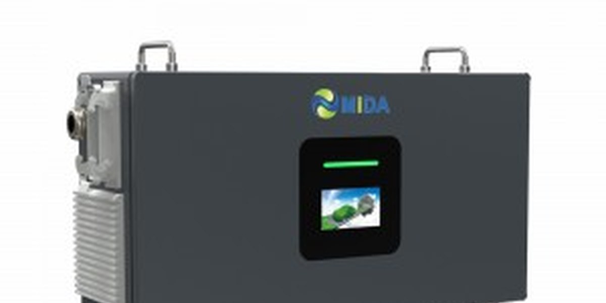
MIDA’s roadside rescue charging station — a battery-equipped DC unit designed to fit inside a minibus — is a useful case because its published data supports a concrete duty-cycle calculation.
| Parameter | Specification |
|---|---|
| Input voltage | 260 – 485 V AC, 3-phase |
| Rated energy capacity | 65 kWh / 125 kWh (published); 40 / 65 / 141 / 161 kWh option set |
| Output voltage | DC 200 V – 1,000 V |
| Output current | 0 – 120 A |
| Energy delivered per hour | Up to 60 kWh |
| Unit self-recharge time | 1 – 2 hours |
| Charging gun cable | 5 m (extendable) |
| Display | 7-inch touch screen |
| Cooling | Wind / liquid cooling |
| Installation | Portable; can be placed in a minibus |
Illustrative scenario (assumption-based, not a MIDA performance guarantee): assume a rescue vehicle carries a 125 kWh unit, performs three service calls in a shift, and delivers an average of 40 kWh per call. That is 120 kWh drawn from the battery — close to one full cycle. With a 1–2 hour recharge between shifts on a standard three-phase supply, the unit can return to service the same day without any grid upgrade at the depot.
The reason this matters commercially is service-level design. The unit’s value is not measured in kWh stored, but in the number of stranded vehicles returned to the road per shift. The roadside rescue charging station specification — 200–1,000 V output covering modern 800 V vehicles, a 5 m extendable cable, and wind or liquid cooling for high-temperature operation — maps directly onto that operational requirement.
For lighter duties, the movable fast charging stations at 7 kW to 40 kW offer IP54 protection, air or liquid cooling, CCS/GB/T/CHAdeMO connector options, and a 5 m cable in a unit that one person can transport. They are built for single-phase or three-phase supplies, which makes them suitable for locations where no dedicated high-power circuit exists.
The Three Principles Behind the Numbers
Storage and solar integration are frequently sold as hardware. The engineering, however, comes down to three operating principles.
1. Peak shaving. The BESS discharges during the site’s highest-demand interval, reducing the maximum grid import. Because many commercial tariffs bill on maximum demand as well as energy, this can reduce cost even when total energy consumption is unchanged. The sizing question is: what is the site’s peak, and how much of it can the battery cover?
2. Self-consumption. Solar generation is used on-site rather than exported. Self-consumption improves when generation and charging demand coincide — which is why solar canopies over charging bays are structurally efficient even when they are not the cheapest form of generation.
3. Demand response readiness. A site with controllable storage and chargers can, in principle, respond to grid signals. The IEA notes that time-of-use tariffs, dynamic tariffs, and aggregator control can flatten load curves and reduce the need for grid reinforcement, while poorly designed static tariffs can cause simultaneous charging and worsen grid impacts. Storage gives a site the physical capability to respond; the tariff and market framework determines whether it is rewarded.
Buyer Guidance: Five Questions Before Specification
- What is the actual grid constraint? A connection limit, a demand charge, or a total absence of supply leads to three different designs. Solar-storage-charging is not a single answer.
- What is the daily energy vs. daily peak ratio? High energy with low peak favours a larger battery cycling once per day; low energy with a sharp peak favours a smaller battery with high discharge capability.
- What is the solar yield profile? Self-consumption value depends on whether generation overlaps with vehicle arrival patterns. A site busy at night benefits less from PV than a workplace site busy at midday.
- What is the site’s future capacity plan? Storage should be specified as the first stage of a scalable design, not as a fixed-size add-on. MIDA’s split DC architecture, with its documented expansion path, is designed for staged growth.
- Who maintains the battery? Cycle life, thermal management and warranty terms determine the real cost of ownership. A storage system is only as good as its service plan.
Frequently Asked Questions
1. What does “solar-storage-charging integration” actually mean? It means combining photovoltaic generation, battery energy storage and EV charging at one site. The battery decouples when energy is generated from when it is consumed, which lets a site exceed its instantaneous grid capacity without a grid upgrade.
2. Why not simply upgrade the grid connection? Upgrades can be slow and expensive, and in some regions capacity is simply unavailable within the project timeline. Storage can be deployed in weeks and scaled later, whereas grid reinforcement may take far longer and is not always approved.
3. How large a battery does a charging site need? Sizing depends on the peak to be avoided, the duration of that peak, and the site’s daily energy throughput. MIDA’s BESS charging stations range from 60 kWh to 2 MWh, so the practical approach is to model the site’s load profile first and match the storage tier to it.
4. Can a mobile charging station really fast-charge a car? Yes. MIDA’s roadside rescue station provides DC fast charging output from DC 200 V to 1,000 V at 0–120 A, delivering up to 60 kWh per hour. It is designed for emergency assistance rather than routine daily charging.
5. How long does the mobile unit take to recharge itself? The published self-recharge time is 1–2 hours on a three-phase input of 260–485 V AC. This allows a unit to complete a shift and return to service the same day.
6. Is solar generation necessary for storage to make financial sense? No. Peak shaving and demand management can justify a battery on their own where tariffs penalize high demand. Solar improves the economics further where generation and charging demand overlap, but it is an enhancement rather than a prerequisite.
7. Are these systems compatible with OCPP backends? MIDA’s DC charging products support OCPP 1.6 and 2.0, which allows storage-integrated sites to be managed through the same charging station management system as conventional chargers. Grid-signal and tariff logic typically resides in the backend, not in the charger hardware.
Capacity, voltage, current and recharge figures reflect MIDA’s published product data. Duty-cycle and cost calculations shown above are illustrative scenario assumptions and must not be treated as guaranteed MIDA performance results.
Post time: Sep-28-2026


