
Quick Answer
The Megawatt Charging System (MCS) crossed a milestone in 2026 when ISO 15118-20 Amendment 1 formally integrated MCS communication procedures and requirements. MIDA answers the same heavy-duty, ultra-high-power demand with a modular split DC architecture spanning 360 kW, 480 kW, 600 kW and 720 kW, and up to 1,680 kW across the wider portfolio. Instead of one oversized monolith, power cabinets are separated from dispensers and share energy dynamically across guns. For site owners the practical payoff is capacity that can be added later, better utilization of installed power, and a deployment path that mirrors how electric truck and bus fleets are actually being electrified today.
Key Takeaways
- Standards caught up in 2026. ISO 15118-20 Amendment 1, published on 17 July 2026, officially integrated the Megawatt Charging System into the standard, added new AC Distributed Energy Resources (DER) services, and strengthened the security architecture.
- MCS is a system, not just a plug. CharIN’s requirements describe a single conductive plug rated up to 1,250 V and 3,000 A DC, Ethernet plus ISO/IEC 15118-20 communication, UL 2251 touch-safe protection, automation readiness, and V2X bidirectionality.
- MIDA scales in modules, not leaps. The split DC family delivers 360 kW, 480 kW, 600 kW and 720 kW with dynamic power distribution, DC 150–1,000 V output, and ≥95% conversion efficiency.
- Deployment risk moves from hardware to planning. Separating cabinets from dispensers lets operators add terminals and capacity without replacing the whole site — a hedge against uncertain early demand.
- Certifications decide feasibility. CCS, NACS, GB/T and CHAdeMO connector variants, plus OCPP 1.6/2.0 backend support, determine whether a site can actually be commissioned in a given market.
Electric truck sales more than doubled in 2025 versus 2024, reaching 9% of all truck sales worldwide, according to the IEA’s Global EV Outlook 2026. The same report notes that electric trucks remain two to three times more expensive to purchase than diesel equivalents, while total cost of ownership is already competitive in China and is expected to reach parity in Europe by 2030. That combination — more heavy vehicles, tighter margins, and compressed dwell time at depots — is the exact pressure that pushes charging architecture from “how many kilowatts” to “how intelligently those kilowatts are shared.”
What the MCS Standard Actually Changed in 2026
The MCS has been a CharIN initiative since 2018, when the association formed a dedicated Task Force to define a high-power charging solution for heavy-duty vehicles. The system was always designed as an extension of the Combined Charging System (CCS) rather than a replacement, so that existing engineering building blocks could be reused and time-to-market shortened.
Two developments define the 2026 landscape:
- Formal standardization. ISO 15118-20 Amendment 1 was published on 17 July 2026. It introduces dedicated communication procedures and requirements for MCS, enabling standardized high-power charging communication for heavy-duty vehicles and other megawatt-scale applications.
- Bidirectional energy services. The amendment also incorporates new AC Distributed Energy Resources (DER) services, strengthening bidirectional interaction between vehicles and the grid and supporting advanced smart charging and energy management use cases.
CharIN’s stated requirements for MCS — still evolving — describe an ambitious interface: a single conductive plug, a maximum of 1,250 V and 3,000 A DC, Ethernet communication paired with ISO/IEC 15118-20, UL 2251 touch-safe design, an on-handle software-interpreted override switch, UL (NRTL) certification, cyber-security, and V2X bidirectionality. Connector vendors such as Stäubli have demonstrated rated currents up to 2,000 A with limited cooling needs, and a 2020 NREL cross-industry event tested seven vehicle inlets against eleven charger connectors — evidence that MCS interoperability is validated hardware-first, not marketing-first.
For a buyer, the takeaway is simple: MCS is real, but it is a high-power class, not a single product. The megawatt connector is the top of a spectrum. Most commercial fleets today live far below it.
From Megawatt Ambition to Modular Deployment: MIDA’s Split DC Architecture
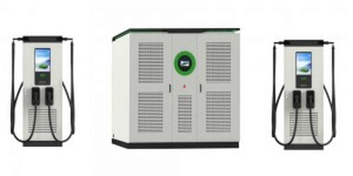
MIDA’s answer to the same problem is architectural rather than aspirational. A split DC charging system separates the power conversion cabinets from the user-facing dispensers. Power modules live in a central cabinet; dispensers are slim, low-maintenance columns placed where drivers actually park. The two are connected, and power is allocated dynamically across guns.
MIDA’s split-type DC fast charging portfolio spans 360 kW to 1,440 kW, with the mainstream commercial configuration covering 360 kW, 480 kW, 600 kW and 720 kW. The same modular logic runs through the wider MIDA portfolio: floor-standing DC fast charging stations from 60 kW to 480 kW, wall-mounted DC chargers from 20 kW to 80 kW, and mobile DC units from 7 kW to 60 kW.
How dynamic power distribution changes site economics
Dynamic power distribution is often described as a feature. It is better understood as a power-budget management strategy. In a conventional site, each charger has a fixed ceiling, and vehicles that draw less than their ceiling waste the difference. In a split architecture with dynamic distribution, the cabinet’s total capacity is shared: when one vehicle tapers, another can absorb the released power.
The consequences are measurable in operations:
- Higher average power utilization from the same electrical service, because capacity is pooled rather than partitioned.
- Fewer grid upgrades at the design stage, since the site can be specified against aggregated rather than worst-case simultaneous demand.
- Graceful degradation. If one power module fails, remaining modules keep the site operating — a critical difference for highway and fleet depots where downtime is measured in lost vehicles, not lost transactions.
Reference specification: MIDA split DC fast charging system
| Parameter | Specification |
|---|---|
| Output power (family) | 360 kW / 480 kW / 600 kW / 720 kW |
| Output voltage | DC 150 V – 1,000 V |
| Output current | Single gun: DC 0 – 300 A |
| Conversion efficiency | ≥ 95% |
| Input | AC 400 V ±10%, 47/45–65 Hz, 3-phase + N + PE |
| Power factor | ≥ 0.98 |
| Current THD | < 5% |
| Cooling | Air / liquid cooling |
| Protection class | IP54 (outdoor) |
| Cabinet dimensions (W×D×H) | Approx. 1,300 × 900 × 2,300 mm |
| Cabinet weight | Approx. 1,000 kg |
| Module weight | Approx. 20 kg |
| Cable length | 5 m (customizable) |
| Operating temperature | −30 °C to 50 °C (derated 50 °C to 70 °C) |
| Storage temperature | −40 °C to +70 °C |
| Altitude | ≤ 2,000 m |
| Display | 10-inch |
| Start modes | Plug and Charge, card swipe, QR scan (optional) |
| Billing modes | Fixed energy / fixed amount / fixed time (optional) |
| Connector standards | CCS, GB/T, CHAdeMO, NACS |
For comparable mainstream commercial DC charging piles, MIDA’s floor-standing range covers 60 kW, 80 kW, 120 kW, 180 kW, 240 kW and 320 kW with single-gun current up to 300 A and the same DC 150–1,000 V envelope, which keeps connector and cable choices consistent across a mixed site.
Matching Charger Class to Vehicle Class
The most common pre-purchase error in high-power charging is over-specifying. A depot serving delivery vans does not need a 720 kW cabinet; a highway corridor serving long-haul tractors does not benefit from a 60 kW column. The table below maps typical MIDA charging classes to realistic duty cycles.
| Charging class | Typical output | Representative use case | Why it fits |
|---|---|---|---|
| Mobile / wall-mounted DC | 7 kW – 80 kW | Roadside assistance, apartments, villa garages, overnight depot top-up | Low site power, minimal civil works, fast to deploy |
| Floor-standing DC | 60 kW – 320 kW | Public parking, hotels, fleet depots, retail hubs | Balanced cost per kW and per connector |
| Split DC system | 360 kW – 720 kW | Highway corridors, truck stops, bus depots | Dynamic power sharing across multiple guns |
| Liquid-cooled / ultra-high power | 600 kW – 1,080 kW+ | High-frequency fleets, heavy-duty corridors | Sustained high current with cable cooling |
The IEA notes that fewer than 5% of the electric car stock can currently use chargers above 250 kW, but that this share is growing alongside ultra-fast and megawatt-scale deployment. In practice, this means a split DC site is usually planned for future vehicles, not only today’s. Modularity is what makes that bet affordable.
What Buyers Should Verify Before Signing
Because the split architecture decouples power from dispensers, procurement reviews should focus on the interface between them. Four checks matter most:
- Dynamic power distribution logic and its documented rules. Ask how power is released when a vehicle tapers, whether allocation is first-come or prioritized, and what happens when a module is taken out of service.
- Expansion path. Confirm the maximum cabinet capacity and how many additional dispensers can be added later without new switchgear. The stated benefit of a split system is “convenient later capacity expansion” — that benefit should be quantified in writing.
- Connector and protocol variants. Specify CCS1, CCS2, NACS, GB/T or CHAdeMO against the target market, and confirm OCPP 1.6/2.0 compatibility for backend integration.
- Environmental rating against the actual site. IP54 is appropriate for outdoor installation, but cable length (5 m standard, customizable), altitude up to 2,000 m, and the 50–70 °C derating window must be checked against local climate.
Standards, Certifications and Test Principles
Standards work is what makes high-power charging commercially repeatable. Three layers matter:
- Communication layer. ISO 15118-20, now amended to include MCS, defines high-level communication, Plug and Charge, and bidirectional services over CCS. OCPP 1.6/2.0 governs the link between charger and charging station management system.
- Connector layer. IEC 62196 defines the mechanical and electrical interface; UL 2251 governs touch-safe design for high-current connectors in North American deployments. MCS specifically requires UL (NRTL) certification, OSHA/ADA alignment, and FCC Class A EMI compliance.
- Safety and environmental layer. IP54 outdoor protection, insulation and withstand-voltage testing, and thermal validation under continuous high-current operation.
Testing principle: high-power charging is validated by sustained thermal and communication conformance, not by peak power claims alone. The industry’s interoperability events — such as the multi-vendor connector testing at NREL — exist precisely because a charger that reaches its rated current on a bench can still fail in the field when cable temperature, connector fit, and vehicle handshake interact.
Frequently Asked Questions
1. What is the difference between MCS and a 720 kW split DC charger? MCS is a standardized connector and communication system for megawatt-scale charging, primarily aimed at Class 6–8 commercial vehicles. A 720 kW split DC charger is a deployable product architecture that delivers high power today using established CCS-class connectors. MCS sits above it in the power ceiling, but both address the same operational need: minimizing vehicle dwell time without rebuilding the grid connection.
2. Does MIDA’s split DC system require a megawatt grid connection? No. The split architecture is designed to distribute a defined cabinet capacity across multiple dispensers. Because power is pooled dynamically rather than reserved per gun, the site can often be served by a lower electrical service than a site with individually rated chargers of equal count.
3. How does dynamic power distribution improve uptime? When one power module is unavailable, the remaining modules continue to serve connected vehicles. In a fixed-per-charger design, a single failure removes an entire charging point. In a modular cabinet, the site degrades in speed rather than stopping.
4. Which connector standards can the split DC system support? The family supports CCS, GB/T, CHAdeMO and NACS variants. Selection should follow the target market: CCS2 in Europe, CCS1 and NACS in North America, GB/T in China, and CHAdeMO where legacy Japanese-standard vehicles are present.
5. What environment can it operate in? The reference specification covers −30 °C to 50 °C ambient operation with derated output between 50 °C and 70 °C, storage from −40 °C to +70 °C, humidity 5–95%, and altitudes up to 2,000 m. The cabinet carries IP54 protection for outdoor installation.
6. Is the system compatible with Plug and Charge? Yes. Plug and Charge, card swipe, and QR-code start modes are supported, with billing modes for fixed energy, fixed amount, or fixed time. For Plug and Charge specifically, the vehicle and charger must both implement the relevant ISO 15118 profile.
7. How should an operator decide between 360 kW and 720 kW? Start from the vehicle duty cycle, not from peak marketing numbers. Count simultaneous high-power sessions, estimate average rather than worst-case demand, and confirm the cabinet’s maximum expandable capacity. If demand is genuinely uncertain, specify the smaller cabinet with a documented expansion path to the larger one.
Specifications cited above reflect MIDA’s published product data for its split DC charging system and floor-standing DC charging piles. Scenario-based planning figures should be validated against site-specific load studies before procurement.
Post time: Sep-28-2026


