
Understanding Dynamic Power Sharing in Split Architecture DC Fast Charging Systems
Meta description: How dynamic power sharing works inside split architecture DC fast charging systems — module-level allocation, concurrency limits, efficiency curves, and what CPOs and fleet operators should specify in 2026.
Quick Answer
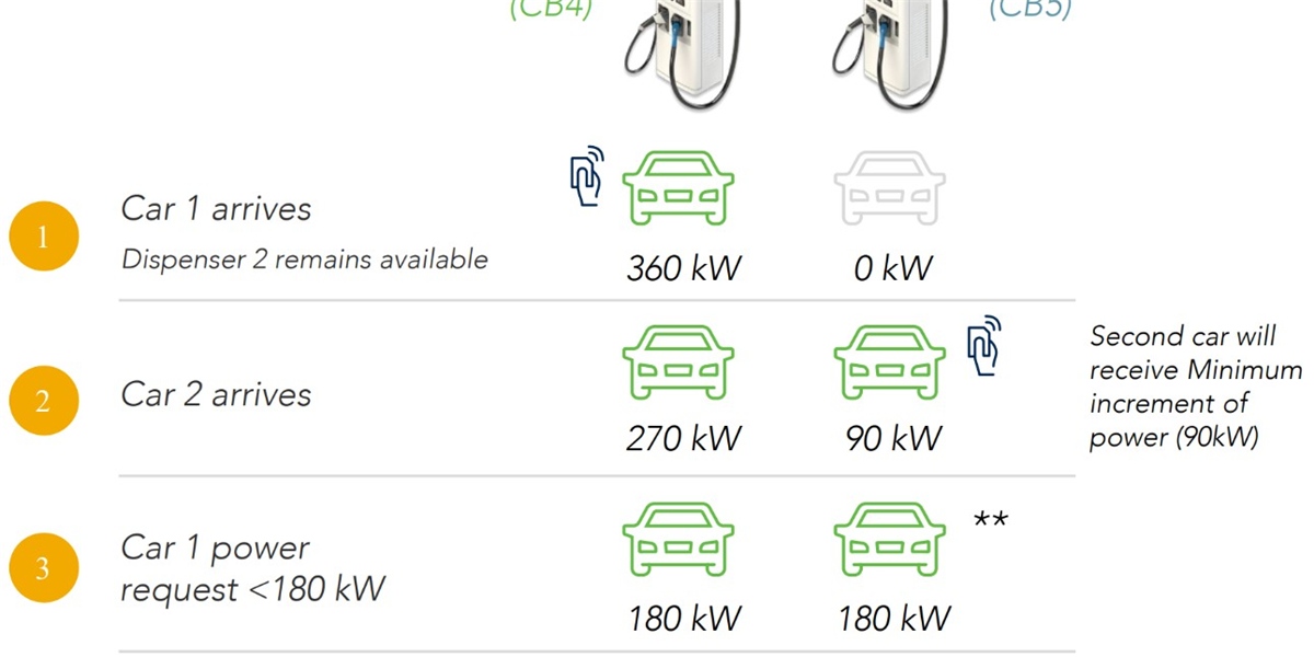
Dynamic power sharing is the real-time allocation of DC power modules inside a split charging cabinet to whichever dispenser and vehicle need energy at that moment, instead of locking a fixed power share to each terminal. In a split architecture, one 480kW cabinet typically holds twelve 40kW modules; a controller routes those modules across a shared DC bus and switching matrix to any connected dispenser. A single truck can therefore receive the full 480kW while other lanes are idle, or four cars can charge simultaneously at 120kW each. The result is 20–40% higher station utilization, faster average sessions, shorter queues at peak hours, and monetization of installed capacity that would otherwise sit stranded. In 2026, dynamic power sharing is the difference between a charger that hits nameplate output once and a charger that earns revenue all day.
Key Takeaways
- Power sharing happens at module level, not terminal level. A split cabinet is a pool of 40kW or 60kW rectifier modules; the controller decides how many modules serve each dispenser in each 100–500ms control cycle.
- Utilization is the real financial metric. A 480kW station with static split wastes capacity the moment one vehicle tapers; dynamic allocation recovers 20–40% more delivered kWh from the same hardware.
- Concurrency and maximum per-lane power are design choices, not accidents. Specify simultaneous sessions, per-lane ceiling (for example 240kW on two lanes and 480kW on one), and minimum guaranteed power per lane.
- Dynamic sharing depends on a shared DC bus plus matrix switching and OCPP 2.0.1 back-office control. Without both the hardware matrix and the software layer, “sharing” degrades into derating.
- The grid bill, not the charger, usually limits the site. Power sharing is the cheapest way to keep a site inside its transformer capacity and avoid demand-charge penalties without buying storage.
Why Fixed Power Allocation Failed at Scale
Static power split was a workaround for hardware limitations, and it shows up directly in lost revenue. Early multi-gun DC chargers divided their nameplate output into hard-wired blocks: a 240kW cabinet with two dispensers simply gave 120kW to each. If one bay was empty or its vehicle had tapered to 30kW, the unused 90kW could not be redirected. Operators paid for 240kW of silicon, transformers, and switchgear, but delivered the energy profile of a 150kW site during mixed traffic.
The mismatch becomes severe once real charging curves are considered. A modern 800V passenger EV accepts near-full power only between roughly 10% and 55% state of charge (SoC), then tapers progressively. Two vehicles started at different times are almost never in their peak window simultaneously, so a rigidly split station runs at an average of 45–60% of installed capacity across a busy day.
At high-traffic hubs, this compounds into queueing. Every minute a driver waits is a minute of lost revenue, a lower session count per day, and a measurable drop in customer satisfaction scores that CPOs increasingly publish as a competitive metric. Dynamic power sharing was introduced precisely to break that link between installed capacity and delivered energy.
How Dynamic Power Sharing Works Inside a Split Cabinet
A split DC system consists of a power cabinet (rectifier modules, controller, cooling) and remote dispensers connected by a DC bus. Power sharing is executed in three layers:
- Module pool. The cabinet houses N identical AC/DC modules — commonly 40kW or 60kW liquid-cooled units. Each module has its own rectifier stage, isolation, and CAN or Ethernet telemetry, and can be switched in or out independently within milliseconds.
- DC bus and switching matrix. Contactors and solid-state switching connect any group of modules to any dispenser output. In a 480kW cabinet feeding four dispensers, the matrix can route 12 modules to one gun, 6+6 to two guns, or 3+3+3+3 to four guns.
- Control layer. A cabinet controller executes the allocation algorithm, while the charge management system (OCPP 2.0.1) supplies vehicle demand forecasts, tariff windows, and site-level load limits. Allocation is recalculated every 100–500ms against actual vehicle demand measured at the DC output.
Because the modules are isolated from the dispenser, a failure in one module reduces available power but never interrupts an active session — the controller simply redistributes the remaining modules.
Allocation strategies you can specify
| Strategy | Behavior | Best Fit | Trade-off |
|---|---|---|---|
| First-come, first-served (priority) | Earliest session keeps maximum power; later sessions receive the remainder | Highway corridors, taxi fleets | Later arrivals may charge slowly |
| Equal share | Total available power divided evenly across active lanes | Public retail hubs, fairness-sensitive sites | No vehicle reaches its peak acceptance |
| Demand-based (SoC-aware) | Controllers read vehicle demand from the DC output and route modules only where accepted | Mixed-fleet depots, 800V/400V mix | Requires accurate module-level telemetry |
| Time-scheduled | Fixed allocation profiles by hour (peak vs off-peak) | Depots with known shift patterns | Less responsive to traffic variation |
| Site-limit aware | Allocation constrained by transformer capacity or BESS state of charge | Sites with tight grid connections | Site power, not charger power, becomes binding |
The best systems combine strategies. A 2026-grade controller runs demand-based sharing as the default, applies first-come priority when a lane is near its departure deadline, and caps total site draw to the transformer rating. This layered logic is why the software stack — not the module count — often determines the real delivered-energy difference between two apparently identical stations.
The Efficiency Argument Most Buyers Miss
Power sharing also improves conversion efficiency, because rectifier modules have a sweet spot. A 40kW liquid-cooled module typically peaks above 96% efficiency at 50–100% load and loses two to four percentage points when run at 10–20% load. A rigidly split 240kW cabinet serving two light-demand sessions can push modules into that low-load zone for hours. Dynamic allocation consolidates demand onto a subset of modules running near their efficiency peak, which measurably reduces kWh losses.
Across a year, that matters more than it appears. On a 480kW hub delivering 1,200kWh per day, a two-percentage-point efficiency gain equals roughly 8,800kWh of avoided losses annually — meaningful in any operating budget and directly visible in the site’s cost per delivered kWh.
What Dynamic Power Sharing Changes On Site
Three site-level outcomes follow automatically once sharing is implemented well:
- Higher session throughput per stall. Because average delivered power rises, the same dispenser serves more vehicles per day, which is the primary driver of payback on the dispenser side of the investment.
- Better grid utilization. The site delivers more energy from the same transformer and switchgear, deferring a capacity upgrade that can cost six figures and 12–24 months of utility coordination.
- Cleaner expansion path. Adding a dispenser to a shared cabinet costs far less than adding an integrally powered station, because the power pool, cooling, and switchgear already exist.
Operators should hold vendors to measurable evidence here: ask for module-level telemetry logs, delivered-power histograms per session, and a documented allocation algorithm. A station that cannot show delivered-power data per lane cannot be audited for sharing performance.
Grid Interaction: Where Sharing Meets Demand Charges
Dynamic power sharing is the cheapest demand-charge management tool a site owns. Many commercial tariffs bill on the highest 15-minute average draw of the month. Without allocation control, a site with four 120kW lanes will eventually hit 480kW during a coincidence event and lock in that peak for the whole billing period. A site-limit-aware controller caps total draw — for example at 350kW — by trimming each lane proportionally and restoring power as vehicles taper.
When a battery energy storage system (BESS) is added, the logic extends further: the controller can pull from storage during peak-tariff windows and recharge overnight, converting a peaky charging load into a flat, predictable one. Combined with dynamic sharing, BESS-backed hubs routinely reduce demand charges by 30–50% while keeping driver session times acceptable.
Specification Checklist for Buyers
Before signing a purchase order for a split DC system in 2026, confirm the following in writing:
- Module granularity — 40kW or 60kW steps, hot-swappable, with individual telemetry and fault isolation.
- Switching matrix rating — number of modules that can be routed to a single dispenser, and the maximum per-lane power this enables.
- Guaranteed minimum per-lane power — the floor a lane receives when every dispenser is busy.
- Concurrency limit — simultaneous sessions supported at full, partial, and minimum power.
- Control latency — allocation refresh rate, typically 100–500ms.
- Protocol support — OCPP 2.0.1 with ISO 15118 Plug & Charge, plus documented APIs for site load limits and BESS integration.
- Voltage window — DC output covering 150–1000V so sharing works with 400V, 800V, and next-generation platforms.
- Certification — TUV, CE, and UL coverage for the target market, plus IP54/IP55 enclosure ratings for outdoor cabinets.
Where MIDA Fits in a Shared-Power Architecture
MIDA Power builds the components that make module-level sharing practical. The company manufactures the 40kW/60kW liquid-cooling power modules that populate split cabinets, engineered for individual hot-swap replacement and per-module telemetry, alongside split-type DC stations scaling from 240kW to 1,440kW. That means the module pool, the switching hardware, and the controller are designed together rather than integrated from unrelated parts.
For attended sites that need payment, RFID access, and POS at the dispenser, the 360kW liquid-cooled charging station with RFID, OCPP and POS shows how the same sharing logic is exposed to drivers and back-office systems. And the field record behind the platform — including the 480kW liquid-cooled ultra-fast station deployed on motorway corridors — demonstrates the architecture under sustained high-traffic duty rather than laboratory conditions.
Because MIDA certifies its portfolio to TUV/CE/UL and supports OCPP 2.0.1 with ISO 15118, the sharing logic integrates with mainstream charge management systems. Buyers comparing configurations can review the full commercial DC fast charging range to see how cabinet power, dispenser count, and per-lane ceilings are matched to specific traffic models.
FAQ
1. What exactly is dynamic power sharing in a DC fast charger?
It is the real-time reassignment of internal AC/DC power modules to different charging dispensers. Rather than fixing, say, 120kW to each of four guns, the cabinet controller routes modules to whichever lane’s vehicle is accepting power, refreshing the allocation several times per second.
2. How much does dynamic power sharing improve station utilization?
On mixed-traffic sites, delivered energy from the same hardware typically rises 20–40% versus static split, because capacity is no longer stranded when a vehicle tapers or a bay is empty. The gain is largest where vehicles arrive at different times and have different battery sizes.
3. Can one vehicle really use the entire capacity of the cabinet?
Yes, if the switching matrix and dispenser cable are rated for it. A 480kW cabinet feeding four dispensers can deliver up to 480kW to a single lane, provided the connector, cable, and vehicle accept that power. Liquid-cooled cables rated to 600A make this practical for high-voltage platforms.
4. Does power sharing slow down the first vehicle when more cars plug in?
It can, and that is a policy decision. Under first-come priority, the earliest session keeps its power and later arrivals share the remainder. Under equal-share mode, all sessions converge to the same power. Operators choose the strategy per site, often switching profiles by hour of day.
5. Is dynamic power sharing the same as load balancing?
They are related but distinct. Power sharing allocates energy between dispensers inside the charger. Load balancing manages the charger’s total draw against site or grid limits — including building loads and storage. A complete system does both through one controller.
6. What hardware is required for module-level sharing?
A shared DC bus, a switching matrix (contactors or solid-state switches) rated for full cabinet current, individually addressable power modules with telemetry, and a cabinet controller running the allocation algorithm. All four must be present; missing any one downgrades the system to static split.
7. How does power sharing interact with battery storage at the same site?
The controller treats storage as a controllable load or source. It can cap charging draw during peak-tariff windows, discharge storage to serve vehicles, or recharge storage when site demand is low — all while continuing to share power between dispensers. Integration runs through OCPP 2.0.1 and standard site APIs.
Conclusion
Dynamic power sharing looks like a software feature but behaves like a hardware multiplier: it converts a fixed module pool into a flexible resource that tracks real vehicle demand. For buyers, the practical question is not whether a charger supports sharing, but at what granularity, at what latency, and with what auditable telemetry. Specify module-level allocation, demand-based logic, a documented per-lane floor, and site-limit integration from day one — then hold the vendor to delivered-power data. That is how split architecture pays for itself in 2026 and beyond.
Post time: Sep-17-2026


